Scrapping a crap UPS and trying to make a bench PSU from the transformer. (Waste of time)

My Trust UPS battery failed on me last year and I was meaning to replace it but the cost of a replacement battery is almost equal to the cost of a cheap brand new UPS from dubious brands. I’ve always used APC SMART ups’s as they are very reliable and never seem to go wrong but man they are expensive.

Notice the blu-tak over the beeper that was annoyingly loud.

APC do some cheaper models in plastic casing but they are no better than the cheap Trust / Belkin / Mustek types that often advertise with a massive VA rating but are yet much smaller than their APC equivalents. They often only have a 7 to 9Ah battery in them even in 2200VA models. I doubt they would last long at full load and I don’t just mean the battery. They only have 4 MOSFETS at the most which will likely explode the moment it switches to battery at full load.

UPS transformer made by Viking part no 080-44523-00

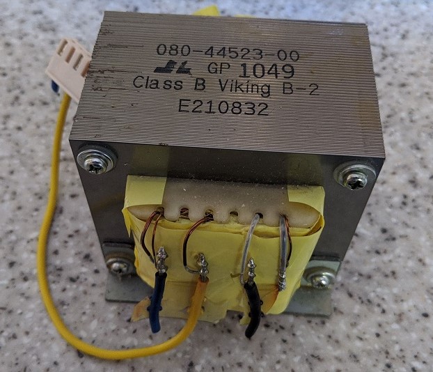
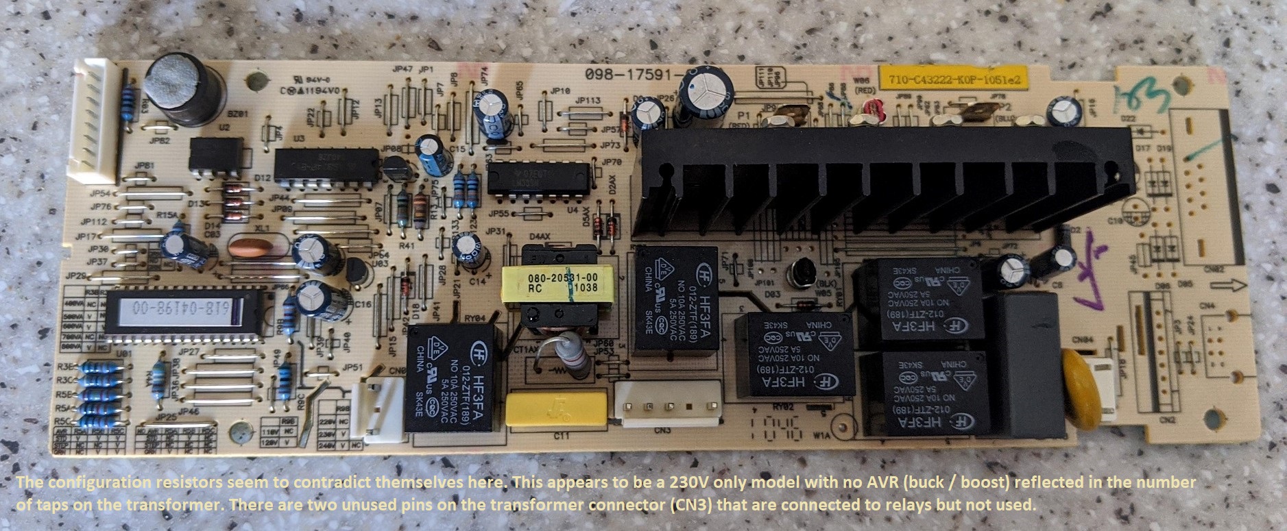
Anyway enough intro. I decided my UPS was just crap and not worth repairing; it was rated at 800VA and had a single 12V 7.2Ah battery in it with an advertised full load runtime of 5 mins. I pulled out the mainboard and noticed that it obviously uses the same board for different models with the configuration set by resistors. They seem to contradict themselves but from what I gather my UPS is set for 230V fixed with no AVR (buck / boost) and 600VA rating. No wonder it had a shit fit when I tried to put more than 600VA load onto it. Definitely said 800VA on the front and the box. Going by the transformer it is a offline / standby type although the board supports some kind of auto voltage regulation though it isn’t line interactive. There are two pins on the transformer connector connected to relays and other electronics but are not used. Perhaps by changing the transformer and configuration resistors you can make it a 220V model or one with AVR that switches taps on the transformer to maintain a stable output voltage without switching to battery.


Continue reading →

Animated clock using 16×32 bi colour LED matrix modules

I finally got round to finishing the improved version of my earlier pong clock which used two single colour 16×24 led modules with a built in controller. This version can display 3 colours and has several different modes to the earlier version and also it can display scrolling graphics from the popular retro game, pac-man. I’m calling this an arcade game clock as the main mode is pong and is inspired by old late 70’s and early 80’s arcade machine games. The case I originally was going to use got damaged but I’ve managed to put the prototype into an Ikea deep photo frame instead.

Now on to the electronics and in particular the LED modules I used. They are kind of standard but nothing like you would typically find on ebay however the firmware can be adapted to work with standard HUB75 1/8 scan modules. Unlike the modules used in the previous clock they do not have a built in controller and all multiplexing etc has to be done in software.

Continue reading →

New LED pong clock version coming soon

Well time certainly seems to fly and it’s the end of another year. It’s been a year since I finished my LED animated Pong clock which I initially started about 3 years ago and I’ve been working on an improved version using bi colour LED matrix modules I obtained from a scrap advertising LED board. It’s a slight improvement over last year’s version but it has some issues that still need ironing out. I’ll post a further update and release the source code later when I feel it’s ready. Happy new year everyone!

12V lead acid battery tester completed

Modified tester for 12V – the load resistors and relay / power board have been moved to an old inverter case.

I mentioned before I was going to make a 12 volt lead acid battery tester at one point. I’ve repurposed the single AA tester I had made back in 2017 and converted it to test higher voltage batteries. Without repeating myself from earlier posts I have just decided to keep this short and just put the 12V tester version on the original project page rather than creating a new one. It works just the same as the AA version in that it displays total runtime and approximate Ah capacity. It is a cut down version of my 24V lithium battery tester which I made for work. The original project page is here. You will want to scroll down to the latest updates section where you will find the schematic and code.

Multiplexing seven segment displays on an Arduino

I’ve made a few projects that use 7 segment displays with methods involving both using a chain of shift registers and multiplexing using the sevenseg library. In my most recent project I’d used 4x shift registers to drive 4 displays which worked well but was a pain to connect up and needlessly complicated. I have used multiplexed methods before but for only 2 or 3 digits but in my recent project that uses 5 digits the display became unacceptably dim.

This is down to how the displays are scanned – in the one shift register per digit method the data is sent to the registers and the latch enabled. 220 ohm resistors were used giving a current for each segment of around 16mA for the LED modules I’d used. For multiplexing only one shift register is used and the digits turned on and off again in sequence but done so fast the eye does not notice. This is a simpler solution and cuts down on components but it does have some things to bear in mind.

I noticed whilst looking on the internet hobbyists are having problems with dim displays and / or blown LED modules. I also noticed a lot of example schematics with LED modules directly connected to an Arduino with no current limiting resistors whatsoever. Whilst this may work well in some cases (more on this later) it’s a bad idea.

Let me explain… Continue reading →

A high capacity lithium battery tester with printout

I mentioned a while ago I had made a version of my single AA cell tester which can test high capacity LiFePO4 batteries with a nominal voltage of 24 volts (8 cells) which I had made for work as we supply 30 and 60 amp hour batteries which need to be tested. I have finally got the hardware and software version complete enough to a point where it works satisfactorily so I’m going to mention it here.

Arduino based 24V battery tester
Completed tester showing the load bank box, controller and finally the Epson TM88 printer on the top

The basics

A simple battery tester that puts a load of approximately 5 amps or 10 amps (selectable) onto a battery with a typical capacity of 30 or 60Ah. The tester displays time lasted and an approximate total amp hour / capacity reading and prints the results onto a Epson TM88 series thermal printer. An RTC is included so testing time and date can be stamped onto the result then a receipt can be given to a customer if required etc.

Continue reading →

Arduino pump timer with GLCD

I’ve been making a timer for my garden watering system as I have bought a few cheap timers from Amazon / Ebay in the past but they were either rubbish or went faulty within a year so I decided to make my own. I used a 240×64 graphic LCD salvaged from an old & obsolete HP 9100C digital sender which I have had in my cupboard for around 14 years. It has a standard parallel interface so can be connected to an Arduino easily. The reason behind using such an over the top LCD for such a simple device was because around 13 years ago I intended to make a status monitor for my PC using LCDStudio software to drive it. The LCD was connected to the PC’s parallel port and housed in a project box containing the negative voltage generator (more on this later) and the backlight board. Anyway needless to say I got it to work; you can find some old photos of it in the project notes.

The completed water pump timer

Like many things I never got round to actually using the status monitor partly because the LCDStudio software was not being actively developed and such didn’t work on newer operating systems. Also my new PC didn’t have legacy parallel ports and I could not get it to work with a USB to parallel converter nor a PCI-E parallel card. So it got forgotten about until I decided to see if I could get that screen working on an Arduino. To cut a long story short, I did and made a few test circuits including a text adventure game, serial terminal and a graphic LCD clock. I got bored of that adventure game and had no need for a 40 pixel wide serial terminal nor did I need another clock so I modified the clock into a water pump timer. The LCD screen uses up almost all of the pins on an Arduino Uno / Nano so it wasn’t much use to me for anything else. Said clock code came from a demo for the T6963C library which needed major modification to work on modern versions of the Arduino IDE as it was still using the .pde file extensions.

So on to further details about how I went about making it…

Continue reading →

Further update on battery testers

If you have been reading my blog you will have noticed I made two Arduino based NIMH AA battery testers around 2 years ago. One was the first Arduino project I made but it needed some improvement and as I had mentioned in one of my previous posts I’m really running out of things to make; I don’t want to end up with a load of gadgets I’ll never use. So I decided to revisit some of my earlier projects and either scrap / repurpose them or improve them. The second tester I made does not really need further improvement as I have already done that and it only gets used once in a while. It is sufficient for my needs so I’m not that concerned about it’s shortcomings. This one however I have plans to turn it into a 12V lead acid battery tester but for now I decided to improve the display layout and make better use of the limited 16×2 LCD.

I had already changed the voltage reference from the inaccurate voltage divider method to a TL431 2.5V reference IC so in preparation for the conversion into a 12V SLA tester I have released an updated version of the NIMH tester code with the improved display layout I plan to use for the 12V version. The project page is here.

So next update I will probably show the completed 12V SLA battery tester although I have also been working on a 24V LiFePO4 version of it too which is complete and working but again needs further improvement. That will be shown in a future blog post when I feel the code is release ready. The pump control timer I mentioned before will get a full project page too when I get round to it. The priority now is to convert the AA tester into a 12V battery tester as I have a ton of them to test.

Gas and smoke detector update

A while ago I made a rather silly project as I had a spare MQ2 sensor laying round left over from a previous experiment. I decided to build a circuit that simply displays the analog value from the sensor on a 7 segment display. It was a bit pointless but it did detect gas, farts 🙂 and smoke. I have since modified the project so it displays more meaningful results. I used an example to calculate the parts per million reading from the sensor by using a formula that works it out from the sensor’s response curve. This is found in the device’s data sheet. I still don’t expect it to be accurate but it definitely works.

I’m going to be re-visiting some of my earlier projects and either scrapping or improving them now that I have learnt more about embedded programming and Ansi C / C++.

The original post and modified code is here.

A large animated LED matrix clock with various time display modes

Clock showing pong on my AV stand

Just over 2 years ago I bought an Arduino Uno development board and began to see what I could do with it. I looked online for inspiration and came across this pong clock by Nick’s LED projects. I immediately thought now that’s cool and wanted to make one for myself and set about trying to source the parts. I had difficulty finding the LED panels used in Nick’s clock (I could only find the larger 5mm LED modules) and used ebay’s feature to email me if any of the ones I wanted became available.

I forgot about it for a while and in the meantime I made a few basic projects mainly based on someone else’s code and modified it accordingly then the email dropped in my mailbox that some of the 3mm LED matrixes were now available. I could only get red ones and they took a long time to arrive from China. I also ordered the case made from a jewelry box as suggested by Brett Oliver who is another maker who built Nick’s clock and made his own customisations to it. I don’t know why but I put those parts into a cupboard and forgot about them.

I came across them a month or two back and decided to put the clock together and make a few customisations which included changing some of the modes, adding PIR support so the display turns off when there’s no-one in the room and adding a separate 7 segment display which displays the time when the matrix is off and room temperature when matrix is on.

Anyway that’s the intro, let me show you a bit more about it:-

Continue reading →

I’m still here; a pong clock, SLA battery tester & crappy Chinese fakes…

Just a quick update; I’ve got a couple of electronics projects on the go which should be finished after Christmas. One is a personal project which is a modified version of an animated clock using two 24×16 modules from sure electronics. That displays some pong animations amongst other stuff. It’s still a WIP but I hope to get it completed soon. The other is a modified version of the AA battery tester I built – one of my first projects. I have changed it so that it can test LiFepo4 batteries with a nominal voltage of 24V. It can also be used to test car batteries and other high capacity lead acid batteries. It works but just needs a few tweaks.

Secondly I have returned to the 8051 microcontroller and built a replacement logic board for a 20 year old LED sign which is obsolete. This was for work not personal use so I am unable to post anything on this site about it due to IP reasons but basically the old controller board had around 30 chips on it of circa 1980 which was replaced with a board containing a Silicon Labs C8051F342 microcontroller, a RS232 chip and a couple of logic gates. The board works perfectly replicating the original sign’s functions with the added benefit of a much lower power consumption and faster updating of the displayed data. Of course the biggest benefit is we no longer have to potentially scrap 300+ signs and can continue to support them.

I’ll be posting information on the LifePO4 battery tester and pong clock in the next month or two.

Continue reading →

The useful TL431 chip

I haven’t made any electronics projects for a while now but I was working on some circuits at work that used a TL431 shunt regulator. This chip can be used to provide a 2.5V voltage reference and also 5V with the addition of two 10K resistors between the Ref pin and supply voltage and another to ground. A 470 ohm resistor on the input to the circuit limits current so not to damage anything. I looked at using one to improve the accuracy of one of my previous projects, an AA rechargeable battery tester.

I had made two testers based on completely different designs, the second uses the 1.1V internal reference to calculate the supply voltage which is used as a reference. The former simply uses a 10K resistor attached to the 3.3V out to the vref pin so it is nowhere near as accurate as the second tester I built. The second tester can also test up to 3 batteries at once.


Going back to the first tester I will use one of the TL431 chips to provide a 2.5V reference and hopefully that will improve accuracy as the 3.3V supply is provided by the CH340 on this clone and is far from ‘3.3V’. I don’t expect the accuracy to improve by much but it’s gonna be better than using a supply voltage as a reference as these can vary especially with cheap voltage regulators found on the Arduino clones. As the tester will only be measuring 1.5V max, 2.5V reference is enough. Unless of course you wanted to modify it to test lithium cells in which case you would need to configure the TL431 to provide a 5V reference instead.