More RAF Tornado parts – a look inside the bearing indicator display

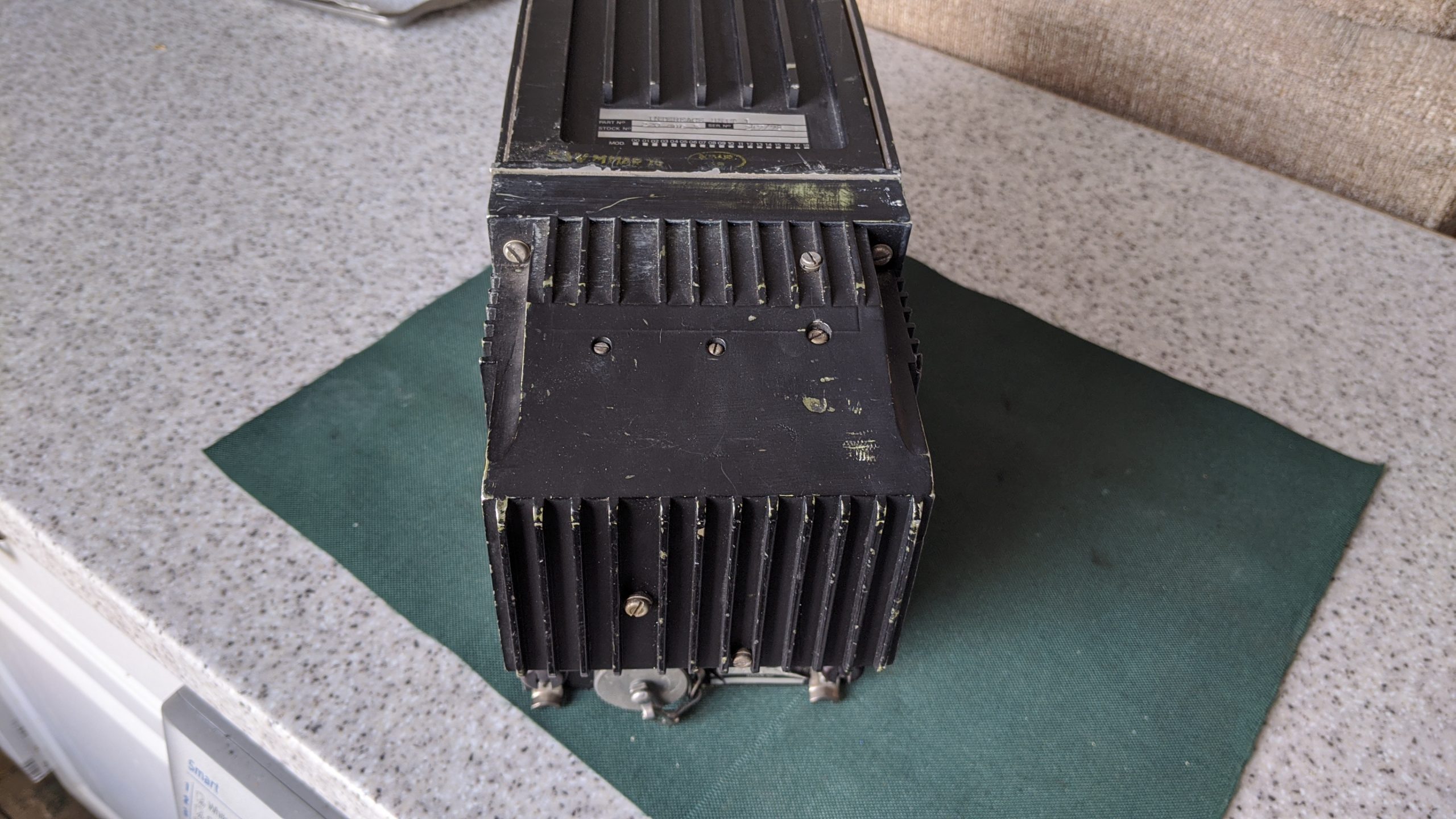
There are a lot of parts from the RAF Tornado on eBay due to them being retired from service back in 2019. I did a teardown on one of the avionics boxes on one of my previous posts which revealed lots of 1970’s silicon tech. Not very impressive by today’s standards but pretty cool to pull apart and see what an aircraft’s avionics consists of. The box itself would make a great chassis to build a bench power supply into once I pull out all the old electronics. Boxes full of 1970’s era electronics were still in use in 2019 although some of the aircraft’s systems were upgraded at some point such as replacing the cockpit displays with colour LCD’s.

RAF Tornado Bearing indicator display

Which brings me on to this item. What this appears to be is a bearing indicator going by the description on the back. This is the display for the Radar Warning Receiver system which shows which direction incoming missiles are coming from so the pilot can release countermeasures and avoid being hit. Many thanks to the curator of BAE Systems’ Rochester Avionics Archive for help in identifying this item. BAE didn’t make the display as the radar division of Marconi who made this wasn’t absorbed into BAE systems. It is a green screen CRT with no video processing circuitry inside the box at all so no composite video input. All the circuit boards consist of is an X deflection board, a Y deflection board both of which appear to be identical and a beam control PCB. The EHT and other high voltage is produced by a module in the top part of the chassis.

Continue reading →

Panavia Tornado Avionics LRU teardown

Whilst browsing through Ebay for weird and obscure things that people sell I came across several sellers selling surplus military and old aircraft parts. Two particular aircraft seem to be the most popular; the RAF Tornado and the Nimrod with the former retired from service in 2019, the latter much earlier back in the early 2000’s. Rather than the parts coming directly from the aircraft scrapyard I think these have been in storage for a long time and have come from avionics repair centres or spares stores as these parts are no longer required due to aircraft retirement. Some of the parts were ridiculously expensive and some were even brand new especially the LCD screens which were fitted during an avionics upgrade back in 2000-2001 I believe?

Anyway, some parts were very cheap and several LRU’s (the black boxes that sit in the avionics bay) caught my eye. I have often wondered how aircraft electronics works and exactly what is inside those boxes and how they communicate with each other. I took a punt on one of the cheapest LRU’s that was complete as a lot of the ex military stuff has had the electronics stripped out and they are literally empty black boxes. The thing I bought was an “Interface Unit 1” which after some searching on google it appears to sit between the main computer and several other systems within the aircraft and external sensors. There was also an “interface unit 2” which looked similar amongst other things which had their electronics stripped out. I presume this was done as the circuit boards were classified; they could have contained ROM’s containing code that was confidential for example. It was also probably to stop reverse engineering, not that anyone would probably want to for something so obsolete and ancient.

Continue reading →

1940’s National watch cleaning machine repair

I was given this machine to repair & restore – a National Electric watch cleaning machine Model 1 which dates from the 1940’s. It was in a very poor condition, rusty and all electrical parts visibly corroded and the original fabric insulation on the wiring had rotten.

National watch cleaning machine
National Watch Cleaning machine model 1

This was a very dangerous machine even when new; they didn’t care much for electrical safety in them days! If you turned it over all the live wiring was accessible as was the rheostat which controlled the motor speed. Simply picking it up whilst plugged in could have resulted in an electric shock. Also the heating element, directly connected to the mains had a jar sat on top of it full of water which is splashed about with an impeller.

I decided that in order to make this thing somewhat safer it would need to be re-wired and some sort of plate fastened over the base to cover the exposed live parts. However upon further inspection I deemed it too unsafe to even plug in so I didn’t bother testing it with power applied. I tested all the parts individually and found that the motor had burnt out with it visibly heavily water damaged and rusted, the power switch was open circuit even in both positions, the rheostat was visibly corroded and the heating element was busted. In short every component on it was faulty with nothing salvageable or repairable at all. It was questionable what I would be able to do with it given the lack of parts, tools and a decent work area as this had to be done on the kitchen worktop.

Continue reading →

A small update to my dual colour pong clock

I’ve released a small update to my arduino controlled dual colour pong clock project (V1.24) which fixes flickering on the seven segment display when the LED matrix is being updated. The change basically stops the matrix from updating when it’s blank as it does not need to. I also made some tweaks to the brightness & colours of certain objects to enhance readability.  The source code can be downloaded here.

20V 1.5A bench PSU with ATtiny85 based electronic fuse

I built a bench power supply for a relative which had to be low cost and I decided to use Bangood as my source of most of the parts to reduce cost. I purchased the case, relay module, DC-DC converter board, panel meter and the output banana jacks from Bangood and the rest came from my spares box. I had a number of issues with these cheap parts as they didn’t work as intended or simply just didn’t work. But more on that later.

The XL4016 based switch mode DC-DC converter board only allowed you to adjust the voltage output and it did not have a current limiter on it. The module is rated at 8 amps output but the tiny heatsinks suggest that it’s probably half that and the transformer feeding it is only rated at 2 amps max. I did a review of the XL4016E1 DC-DC converter module separately; see this link for the first impressions and the flaws I found with it.

This has yet to have the dymo labels fitted and is being load tested.

So I decided to make an auto cutout circuit that works by monitoring the current via an ACS712-5A sensor. The ATtiny85 switches the PSU load on and off via a push button toggle. Useful as the module I’ve used does not have remote off / on facility and it’s handy to turn the output off whilst connecting up your projects rather than having it permanently on. When the output is on the sensor is read and if the current goes above 1.75 amps the output is disconnected and a red LED lights. A green LED indicates that the output is on and all is OK. I used a dual colour LED that simply turns red or green depending on condition. Originally I was going to measure temperature of the XL4016 module too using an LM35 but there were not enough pins on the ATtiny85 and the switching noise from the module produced erratic analog readings that I could not fully filter out. This didn’t present a problem with current sensing however.

Continue reading →

DSN-VC288 voltmeter and current meter review (in short they are shite)

I bought one of the commonly available dual display panel meters with the part number DSN-VC288 which has three digits and shows voltage to 1 decimal place and current to 2 decimal places. It can measure 0-99.9V and 0-10A and features a red display for the voltage and blue for the current. There seems to be several versions of these panel meters; some with 4 digits and some with three. Some of the three digit ones appear to have auto ranging showing voltage to 2 decimal places if less than 10V however mine does not have this facility.

They look smart enough but as everything that is cheap & made in China, they don’t work as intended, are unreliable, poor quality and cannot be used for anything were accuracy is required. There are two ways of connecting these depending on if the supply voltage is different to the voltage being measured or if the meter gets it’s power from the same source it is measuring. In my case I used a seperate supply as the meter stops working below 4V. I definitely did connect it up correctly and have done a bit of research into these.

DSC-VC288 piece of crap voltmeter.

The problems I had was simply the accuracy is way off. It is advertised as 0.1% accuracy for voltage and 1% for current however this definitely isn’t the case. Out of the box, a 5.0V reference voltage measured on a calibrated DVM showed 5.3V and a 20V reference showed 21.8V. On the rear there is a little trimpot so I managed to adjust this to get a reasonable result and now 5V reads 5.0V but 20V reads 20.5V so if this thing can measure up to 100V then the scale appears to be non linear and it is impossible to get an accurate reading throughout the range. I fiddled with it for ages and the accuracy is just unacceptable. In the end I used it to measure voltages up to 20V with emphasis on accuracy being at the bottom end of the scale.

Now as for the current this is a different story. I found that this was showing 0.67A with a 0.5A load and 2.3A with a 2.0A load and the adjustment trimmer was already at the minimum value. The meter does read zero when no current is flowing so the reset trick I found on the web did not work. I also found that some of the component values on the board differ to photos and a schematic I found implying incorrect value components have been fitted.

Continue reading →

Bangood XL4016 adjustable voltage regulator first impressions

I am building a basic power supply for a project and decided to try one of the XL4016E1 based regulator modules commonly available on eBay, Amazon and Bangood which is advertised as being able to handle an 8A / 200W load. I only need up to 2A for my project but at £7.99 it seemed like a bargain and much cheaper than building my own regulator. The one I bought looks like this:-

I bench tested the unit with an input voltage of 30V (the board can handle up to 40V) and subjected it to various loads most of which it handled well. The major issue with this regulator is that it is almost impossible to set the output voltage accurately as the potentiometer is only single turn and the slightest touch makes the voltage jump around. It is very sensitive particularly at the bottom end of the scale e.g if you are wanting to set it to 5.00V then this is almost impossible but say 26.55V then this is easier although it is still difficult. I replaced the potentiometer / switch assembly with a 50K multi turn pot and bridged out the switch pins. The photo below shows the modification I made. The fitted potentiometer was difficult to remove and I inadvertently pulled out some of the board’s through hole plating and tore a PCB trace. I managed to fix this and the board works fine. However even with a 10 turn pot trying to set an exact output voltage to within 10mV was still difficult at the bottom end of the scale.

Continue reading →

Convert cordless drill to lithium battery using RC lipo

Surprisingly even now you can still buy power tools that come with NiCad batteries (not even NiMh) which are a poor choice of battery for power tools due to their memory effect and high self discharge rate. NiMh is a better choice of battery to use but I presume NiMh is cheaper hence why some tools still come with them. I have a bosch drill and hedge trimmer that both use the same type of 14.4V battery which have failed, even the spare one and a cheap Chinese knock off that was bought as a spare. This is simply because they don’t get used often and the batteries self discharge when left in the garage. Upon opening the batteries and checking the cells some of them measured zero volts and were short circuit both in the genuine batteries and the knock off clone battery. Many had leaked too.

Completed bosch drill lithium battery conversion

The internal cells are around the same size of a C size battery but replacing them with NiMH C cells was out of the question as they would not physically fit into the battery casing. As I had a universal RC charger I opted for lipo batteries and charge them using the balance charger but went without the protection board for the low voltage cutoff. This could potentially be a bad idea but I fitted a small bar graph indicator into the battery pack for monitoring the battery voltage. A push button switch connects the indicator across the battery so it does not drain the battery when in storage.

To convert cordless power tools to lithium the correct way would be to use 18650 cells and a proper BMS board as many others have done. This was my original plan but RC lipo battery packs are better suited to high current discharge rates (many 18650 cells are not, the exception being the ones designed for e-cigarettes) and can handle sudden high current spikes. They can also be charged rapidly too. Using cells from old laptop batteries is not a good idea as some will be in better condition than others leading to cell voltages being out of balance. Also they are not designed for high current discharge rates; larger tools may take 20 amps when the chuck is stalled. It’s always best to use brand new cells and a good BMS board. It’s also worth mentioning that if a BMS board is used you must make sure there is back emf protection inside the drill otherwise this will destroy the BMS board when the motor switches off. If the tool does not have such protection across the motor then a small non polarised capacitor of around 10uf should be fitted across the motor. A high power diode in reverse across the battery (after the switch / trigger) should be fitted too. If this is placed across the motor it would be forward biased when the drill is in reverse. This is assuming the drill simply reverses the motor polarity to change rotation direction. I’ve seen several bad reviews for BMS protection boards purchased on ebay / Amazon saying they failed when used for power tool conversion and the lack of the diode and capacitor is almost certainly why they failed.

Here’s some photos of what I did. It’s nothing too fancy as there’s no BMS board or spot welding to do here:-

Continue reading →

Using Arduino to control display module salvaged from LED sign.

I came across someone selling parts from a large LED sign on ebay which by doing some research came from a Data Display LED board originally used for movie name, showtimes and price information display in a cinema lobby. Their part number could be DL110 as that’s the only number I can find on the board. The module I got consists of 12 5×7 LED matrix modules with the shift registers and row driver circuitry so it can be directly interfaced to a microcontroller. Looking at the date codes on the IC’s this thing dates from 1997 / 1998 so is over 20 years old and certainly not something you can buy anymore. Even then it would be a custom part. This was really bought for something to mess around with whilst in lockdown and I do have a possible use for it as a sign to put in the rear window of a car to inform other road users of their driving skills (or lack of)… don’t hog the middle lane you dumbass lol. 🙂

I obviously didn’t have a datasheet but reverse engineering the module by obtaining datasheets for the chips used on the module was fairly easy. The data comes in via a 14 pin connector and goes through buffers then to the row and column drivers. There is another connector for daisy chaining to the next module. I found that the 7 row drive signals come in then go through a 74HC373 latch which was being used as a buffer as it’s relevant enable pins where permanently tied high / low as required. The output enable / latch, clock and data are buffered by AND gates with the two AND inputs tied together. Seems strange how they did this as a schmitt trigger would have sufficed instead. The row drive signals then go on to a mosfet / power transistor driver chip and then finally to the row drive BD436 transistors whilst the rest of the signals go on to the column shift registers.

Continue reading →

A scrolling message display using 3x 16×32 LED matrix modules

This is another unfinished project; I started making a scrolling message display using the LED modules I used for my dual colour Pong Clock around 3 years ago. I managed to get it working to the point where a message can be sent via the serial interface (or a serially connected bluetooth module) and have several display options where you can have big or small text, have it in red, yellow or bold orange. I don’t really have a use for it and the Pong Clock does not get much interest from friends and family as in they don’t want one making so I’m putting the whole lot on eBay over the next few weeks. I’ll keep a couple of modules to play around with or in case someone changes their mind and does want a pong clock making but for now they are done with.

As for the scrolling message display I used modified Adafruit RGB matrix libraries that supports daisy chained modules; I used three for a better and wider display. I don’t know what the maximum number of daisy chained modules you can have but I guess more than three is pushing the Arduino to the limit. The library uses around 1.6kB of SRAM so an Arduino Mega is required even though the code size will fit into the Uno. I’ll release my code for this project for anyone to take and modify themselves as they see fit. Code is being offered without any support, but if you do use the code please credit me. Thanks.

Code for this project Message_Display_16x96

A constant current load using mosfet and LM358

In my below post I mentioned that I am building a bench PSU however I am still waiting for the parts to arrive. I decided to make a constant current load in order to test the electronic fuse and the power supply itself. I had built one before but the mosfet kept blowing after a short time and it was difficult to set the current. I had another go and successfully made one that supported a 1 amp load at 12 volts for over an hour without going up in smoke.

I checked online to see if I had got my circuit right and I had but it was just a bad choice of mosfet. I made a video of it as I have plenty of time on my hands due to the lockdown and I’ve been quite busy finishing projects or finding things to make out of old things I had laying around. A lot went onto ebay and what didn’t sell I threw out or destroyed for a bit of fun.

When the power supply is done I’ll post an update on it. There won’t be much to say as it uses pre built power supply modules but I will be adding some of my own modifications and enhancements such as the abforementioned electronic fuse.

ATmega328 eeprom damaged by power surge?

I had a power surge the other day followed by power cuts that lasted around a second and another about 5 seconds later. Everything seemed OK in the house and even the oven clock was still working and that always reset during a brownout. However my garden watering timer was showing garbage on the LCD so I reset it. I then found that it wasn’t saving the settings for the time and duration of watering the garden. To cut a long story short it appears the eeprom had failed, it was no longer storing it’s settings. I also found a bug in the code whilst I was digging around and fixed that so I’ve updated the download on the project’s page.

I made some changes and made it so that the settings are stored on the eeprom on the ZS-042 module instead and also made another version that stores the settings in a variable in SRAM to get around the problem. I increased the value of the smoothing capacitor on the 5V rail to 1000uf from 220uf and fitted another 0.1uf bypass capacitor near the arduino nano board. Hopefully that will fix the issue. Other than that I may need to change the brownout detection from the default 2.7V to 4.3V. It appears to be working OK now and keeping my garden tubs watered.

I’ve gone over my code and it only writes to the eeprom after the time and / or duration is changed so I don’t think I’ve simply worn it out. The timer worked fine for a year and the eeprom will have been worn out within a week if it was being constantly written to. Just seems a coincidence that I noticed the fault after a power surge. Very strange…