ESP8266 based NTP clock with YouTube statistics display

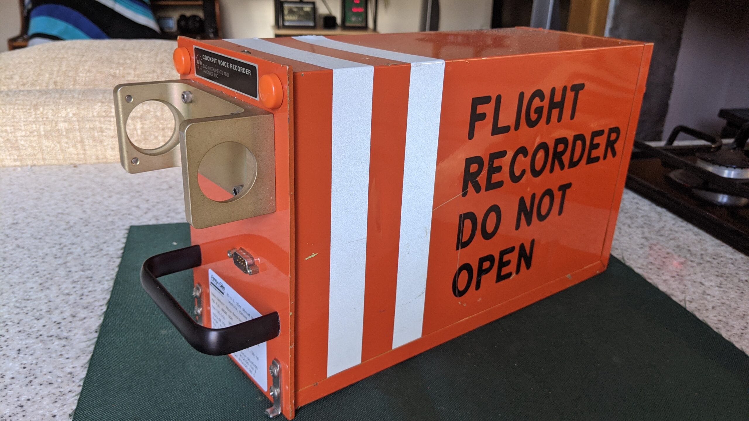
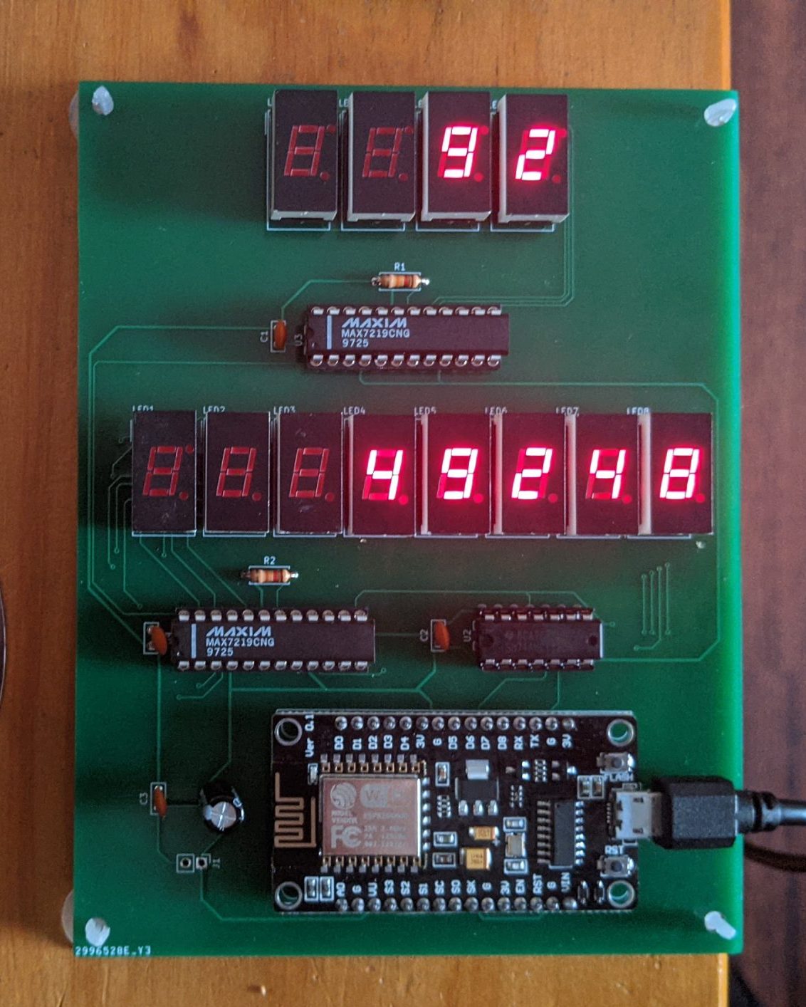
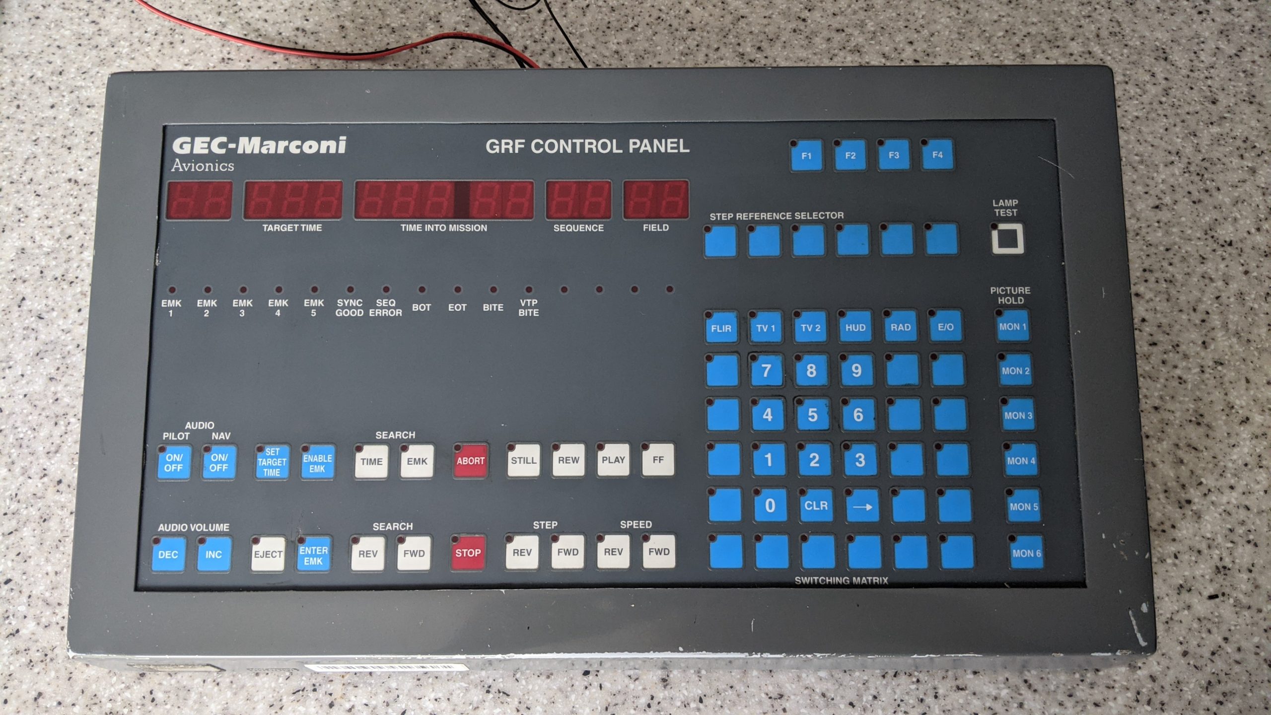
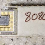
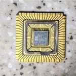
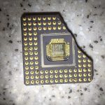
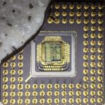
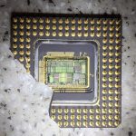
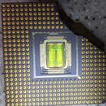
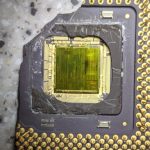
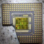
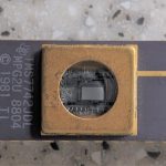
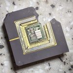
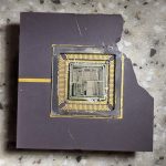
I made some internet connected 8 digit 7 segment LED displays using a NodeMCU and Harris semiconductor ICM7228A LED driver ICs the latter of which were salvaged from old aircraft avionics. As the chips would unlikely sell on eBay I decided to make them into a project and improve upon my earlier YouTube counter project which displayed the subscriber and view counts on a 4 digit and 8 digit LED display.

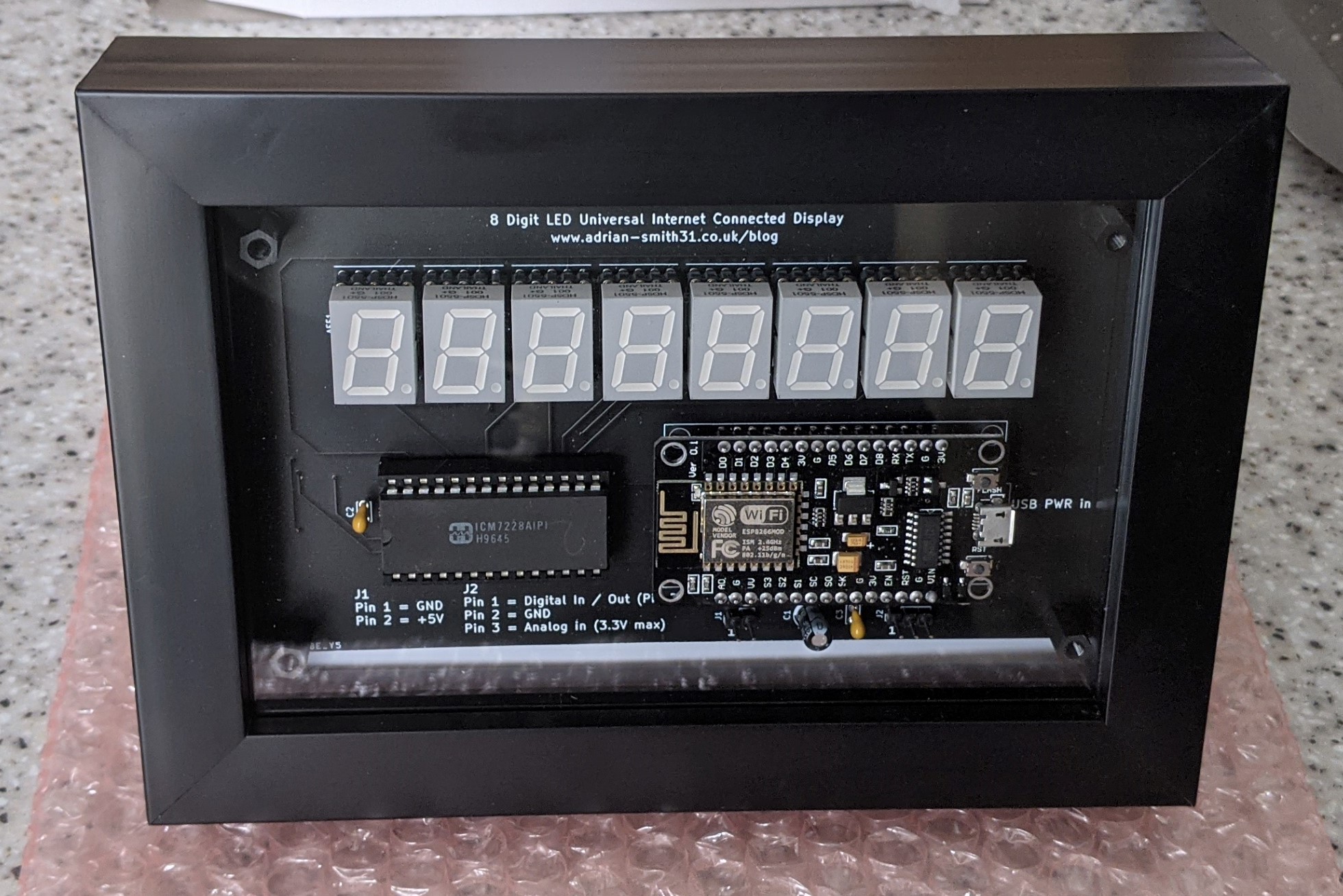
This version uses a 8 digit 0.56″ LED display and shows the current time by default which is obtained and set automatically by querying the NTP servers available on the internet. A button on the rear selects the mode to display; clock, number of YouTube subscribers to your channel and total number of video views. The button also toggles DST on and off by pressing and holding the button for more than 5 seconds and releasing it.

I fitted the completed PCB into a photo frame to complete the project and able to display it in my home. I have made full instructions available to download if you wanted to make one yourself and I also have a limited number for sale (now sold out!) on eBay which you can purchase by going to the links down below. Please note that you will need to obtain a YouTube API key for the YouTube statistics functions to work. This is free of charge but requires a little work on the Google developers page.

To sum up this unit is an universal 8 digit internet connected display which could be used for a number of things but in this example it is loaded with firmware to display the time from the NTP time service and also provide YouTube statistics of your channel showing subscriber count and total video view count. Due to YouTube’s limitations implemented in 2019 the counter will only show exact numbers of subscribers up to 999. After that it will begin rounding them down on a sliding scale starting with the lowest 10. For example 1234 subscribers will show as 1230 and 12345 subscribers will show as 12300 subscribers. Hence this product is suitable for small channels and producers who want to keep an eye on their subscribers as well as know the time!

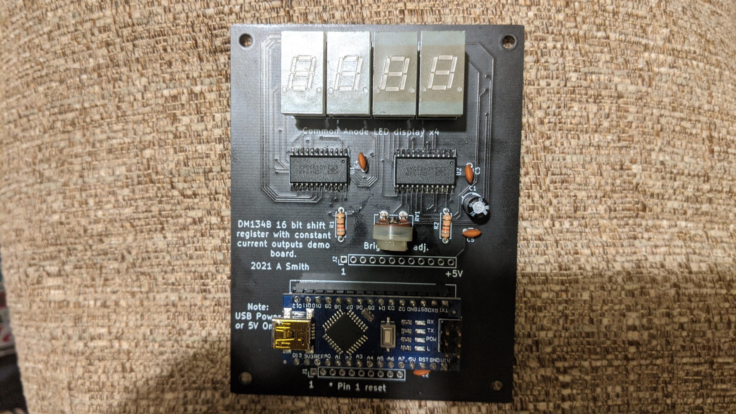
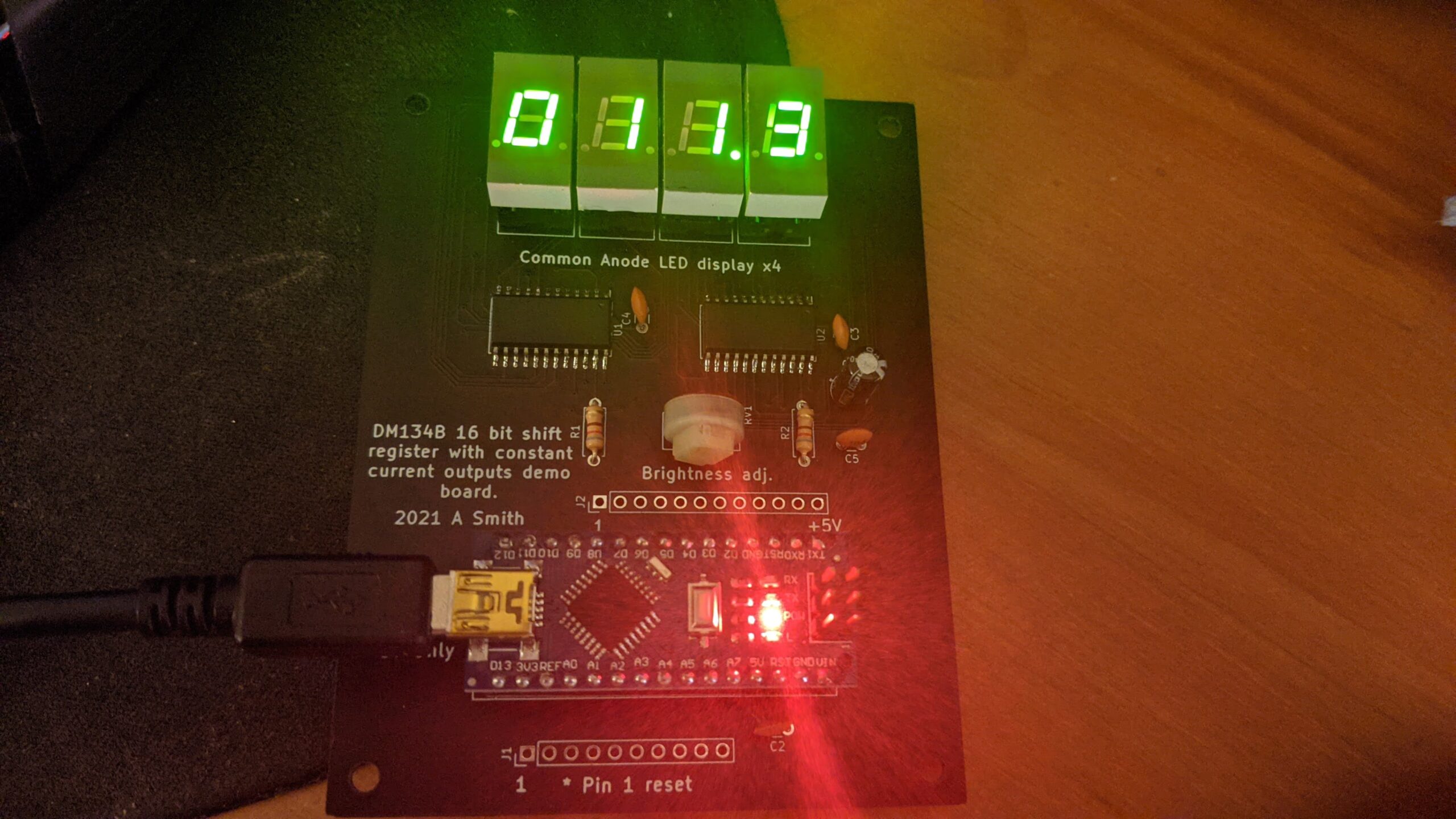
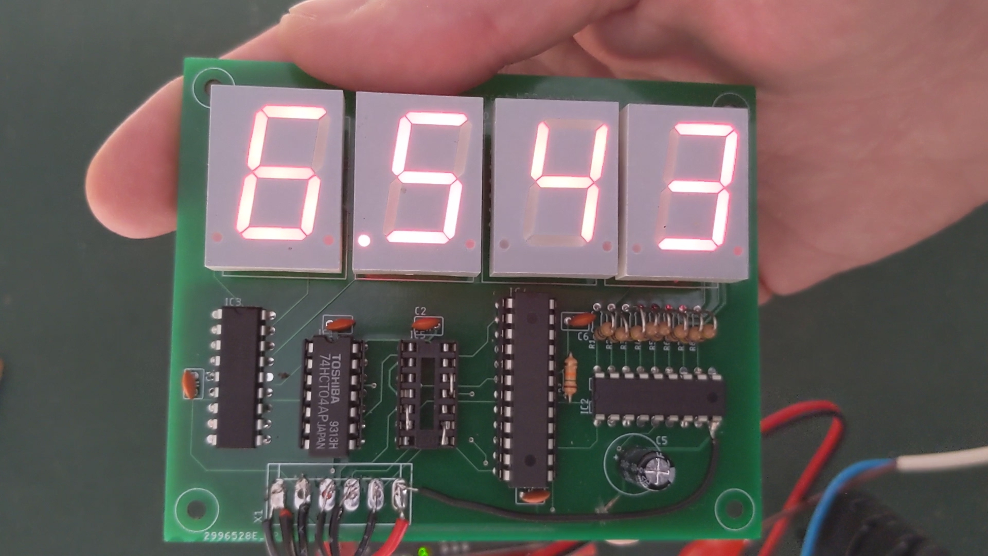
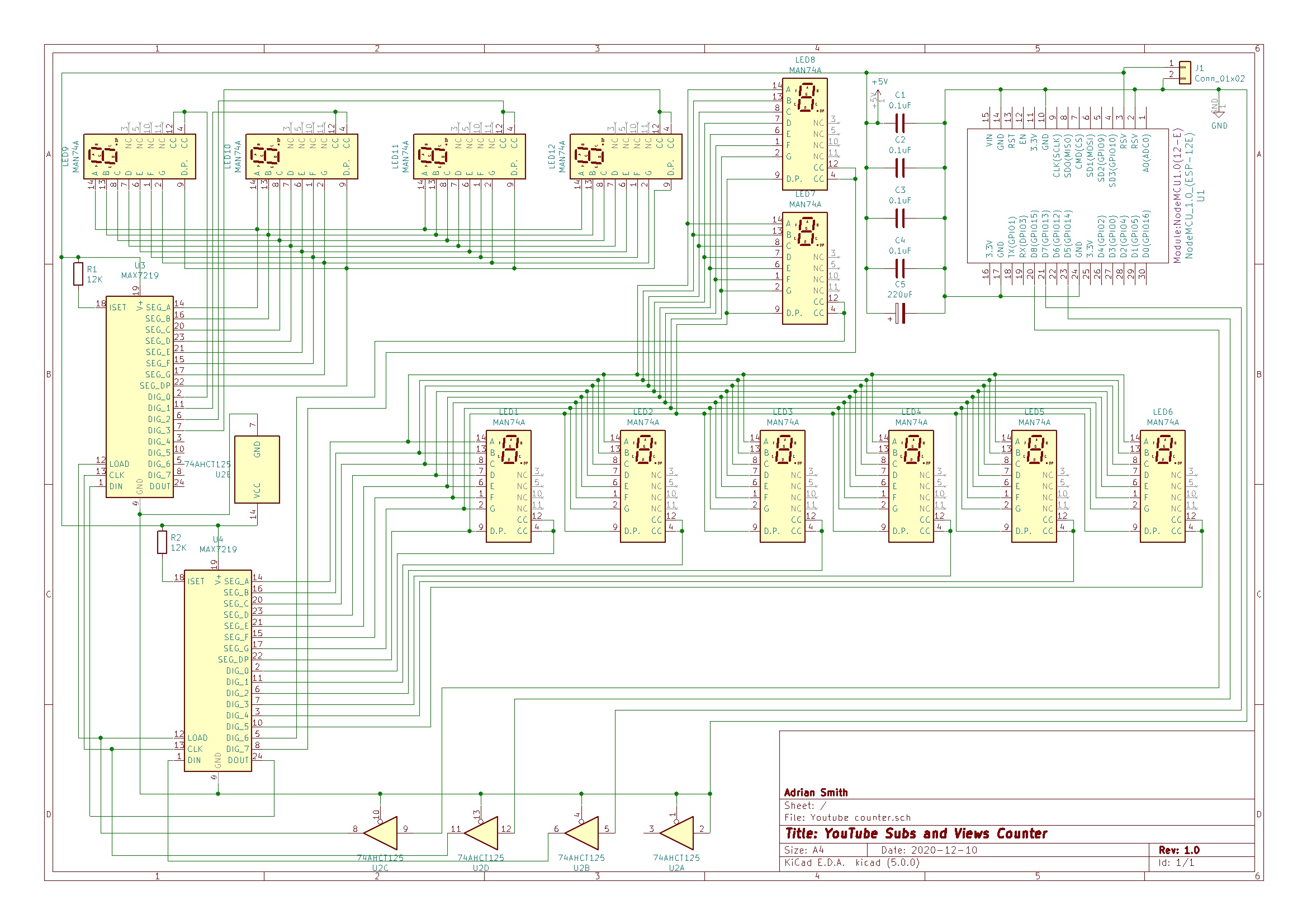
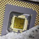
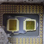
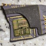
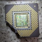
The counter works by connecting to the internet through an ESP8266 WiFi module which has a 32 bit RISC-V CPU onboard running at 80Mhz with some spare flash space for user programs which can be programmed in C++ or Python. This is where the firmware for operation is stored. An ICM7228 display driver chip handles the multiplexing and display blanking and drives 8 common anode high efficiency displays directly without the need for current limiting resistors.

Instructions for use including obtaining API key

YouTube video

Source code

Schematic

PCB design files (KiCad)

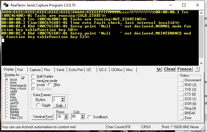
Pre-compiled .bin files (upload using the NodeMCU firmware programmer; esp8266flasher.exe) flash size set to 4Mb, DIO mode @ 40Mhz (not to be confused with CPU clock speed) and flash to location 0x00000. Use 115200 baud.

UK and Europe

Please click on continue reading for the photo gallery.

Continue reading →

The DM134B 16 bit shift register with constant current LED drivers

I have quite a few DM134B IC’s which are 16 bit shift registers complete with constant current LED drivers built in so I decided to make something useful from them. The chips require minimal components; LED current is simply set via an external resistor which is far better than having to use 16 individual resistors. The snag with these chips is that they are surface mount in the SOP-24 package. So to fit them into a prototype board I bought a SOP-24 to DIP converter and soldered one to it and began to experiment with an Arduino and found that they work just fine with the shiftout and direct SPI functions. Just like any other latched shift register.

One chip behaves like two 74HC595’s in series albeit the output enable is active low instead of active high like the ‘595. I wrote a small demo program that counts from 0-999.9 seconds to test them and had some sample breakout PCB’s made in which an Arduino Nano could be fitted to. They worked well so they will definitely be useful for future projects. The demo board contains two DM134B’s daisy chained driving four 7 segment displays which can be used as a voltmeter, temperature readout or indeed any project that needs a 4 digit display. As mentioned above the demo board has space for an Arduino Nano and pins are broke out onto adjacent headers so that they can be used for another purpose such as analog inputs etc.

Here’s the schematic and photos of the demo board. I’ve kept one but the other four I’ve put on eBay as I’m sure they will be useful to someone. The firmware for the demo board can be downloaded here.

Link to Ebay UK where you can purchase these https://www.ebay.co.uk/itm/193904797643

Electronic tape measure using HC-SR04 ultrasonic sensor demo code

Also available on my Tindie store https://www.tindie.com/products/22759/

Instructions (PDF describing the operation and pinouts) DM134B PCB instructions

Video https://youtu.be/-rPsJusRiV0

Schematic:-


A photo of it working:-

Racal Avionics data entry device / CDU teardown and test

This will be the last teardown video for a while and this time I have a Racal Avionics CDU allegedly from an RAF Nimrod which I obtained some time ago and discovered that it communicates with a host system over standard RS422. Now, thinking I might be able to connect it to my PC or an Arduino or any other type of microcontroller I set about seeing how it worked. Armed with a RS422 / RS485 to USB adaptor and an oscilloscope I powered it up (just needs 28V DC) and probed around to see what I could find. The unit does indeed power up and displays a self test screen. Other than being able to control the screen brightness pressing any of the other buttons did not do anything. So I took it apart to see what was inside…


Model number is 80794/SS302 NATO stock number 5826-99-1603965. It dates from around 1990 and uses a couple of Motorola 680x series CPU’s. It appears to be a serial terminal device. There are no ARINC or MIL-1553 buses on this thing although a look at an EPROM dump suggests that is an option. I was unable to get any serial data out of it unfortunately on the RS422 port and even directly on the UART chip itself. I dumped the EPROMS on the boards which reveals that the device configuration is set via straps connected to the rear panel of the unit. However pin 1 was not indicated and what needs to be done with it e.g tie it to ground or +5V. I didn’t get very far with it but I noticed that the CRT is has a line scan rate of 15.625Khz which is the same as analogue European TV’s. Hmm.

Continue reading →

Using large / high current 7 segment LED displays with the MAX7219

I have some largish 7 segment displays which are 0.8″ in height but I found that they were dim when driven from a MAX7219 even at full brightness. I found that this was because the LED displays I were using need around 15 mA for a decent amount of brightness, 25mA ideal. However the MAX7219 only has a maximum peak current of 40mA per segment; now that is peak current so that means with a multiplexed display that will be divided by the number of digits to give an average current of 5mA, or if you prefer the equivalent DC current. Now as my displays need 15mA that simply isn’t enough hence the dim display.

So to get around that problem I used a UDN2982 as a source driver between the segment outputs and the LED segment anodes. 47 ohm current limiting resistors were used (more on that later) and a ULN2803A was used as the sink driver on the digit outputs. Now as the digit outputs will be at a logic low level I had to use an 74HCT04 inverter between the MAX7219 and the ULN2803A as the ‘2803A needs a logic 1 to ‘turn on’ it’s outputs.

I used an LED supply voltage of 7V as 5V wasn’t enough to get a decent amount of current through the displays as the UDN2982 drops about 1.6V across it and the ULN2803A about 1 volt. Together with the voltage drop across the LED display I was only left with 0.4V to play with at a supply voltage of 5V. Both the ‘2803A and the ‘2982 have a absolute maximum current of 500mA for the entire chip so I aimed for 60mA peak current per segment which gives an maximum current through the UDN2982 of 480mA when the worst case scenario of the displays showing 8 and the decimal point is lit. 60mA divided by 8 digits still only gives 7.5mA average segment current – still not enough but as I was using only 4 digits I set the MAX7219 scan limit to only 4 displays which doubled it to 15mA equivalent DC current. This resulted in an acceptable display without overloading the driver IC’s. I did try it on 5V with 6.8 ohm resistors giving around 7mA current but it didn’t work.

Continue reading →

P&G aircraft cockpit voice recorder (black box) teardown

In this teardown video I’ve got something pretty cool; a black box from an RAF Nimrod MRA4 which was a failed project and numerous aircraft were built but were never delivered to the RAF and were later scrapped. This one does show some signs of wear and tear although it may well be damage due to storage and this unit looks like it has never actually been used. The locator beacon on the front which is a circular tube containing a battery and the radio beacon itself is missing however everything else is present.

Penny & Giles Nimrod MRA4 cockpit voice recorder photo.

It is a solid state recorder utilizing 128Mb of flash memory to store the audio recordings and it is buffered and compressed by the electronics to reduce file size and therefore increase recording time. I found the recorder to be functional as I managed to power it up but unfortunately I was unable to access the recordings or the built in serial menu via the RS232 port on the front panel.

The recorder is powered by two microcontrollers; a Philips 80C51 clone which looks like it serves as the boot processor and a 32 bit AMD AM29200-20 as the main application processor. The boot ROM is stored in a 128kb OTP PROM (which I have dumped) and the device’s operating system (probably some kind of RTOS) and the application that actually runs the device is stored in separate 512Kb of onboard flash. This looks like it is flashed / updated via the serial port on the front panel. Unfortunately it seems that this flash has likely been erased to prevent re-use. The firmware that is stored in the 8051 clone chip hasn’t been dumped yet and I’ve yet to determine it’s exact function.

Continue reading →

Clone Wemos D1 mini boards intermittent resetting and other problems

I’ve recently been experimenting with the ESP8266 modules and made a YouTube statistics counter as the first and experimental project. I used a NodeMCU for that which gave me no problems at all. However there is a smaller board, the Wemos D1 mini which on first impressions looks like a more ideal board for final projects and can easily be soldered to veroboard and prototyping boards.

The problem I had was my boards were clones as the originals no longer seem to be made and sellers advertising genuine boards (even showing a photo of the genuine board) are sending clone boards instead. Now that may not seem like a bad thing but I had constant intermittent reboot problems and the board would stick on the bootloader in flash mode if the 5V supply rail was ever so slightly above 5V. That meant it would boot connected to some devices that provide USB power and not boot on others.

This was driving me nuts and I wasted a lot of time trying to find the problem thinking my code was at fault believing the intermittent reboot was due to a stack overflow. I came across this reddit post https://www.reddit.com/r/esp8266/comments/9iizx4/warning_clone_wemos_d1_minis_with_only_150ma_33v/ which shows that mostly these clones come with voltage regulators that cannot handle the load the ESP8266 puts on them. Uh oh.

This post is dated 2018 and a quick look at my boards, from different sellers had voltage regulators marked 4A20 which indicates it can supply a maximum current of 150mA. However the ESP8266 draws a peak current of 430mA especially at boot.

Continue reading →

Aircraft instrument teardown TCAS / TCRD LCD display unit

I obtained for teardown via the wonders of eBay another aircraft instrument. This time it’s a Honeywell LCD display unit that can be used as a TCAS (Traffic Collision and Avoidance System) display or TCRD display. It is for older aircraft that do not have glass cockpits that need to have a TCAS system installed as otherwise such TCAS data would be shown on the main MFD’s. This unit is actually from a helicopter and has modified firmware to turn it into a TCRD display which I’m not entirely sure what that is. I think it stands for Torque Cruise RPM Display but I stand corrected if anyone knows otherwise.

It’s a well engineered unit consisting of a couple of power supply boards, an analogue board and a couple of processor boards containing a custom ASIC and FPGAs with the main CPU being a TMS34010 which is actually a combined CPU and GPU. It is capable of generating 2D graphics for the various symbols and graphics needed to display the data. This chip was used in several arcade cabinets of the late 80’s and early 90’s including the Terminator 2 game cabinet. Which is kind of cool. Speaking of which data is supplied over the ARINC-429 bus and this device generates all of the graphics required; it is a fully self contained computer system in a tiny box. The only disappointment with this is that it runs off 115V 400Hz rather than 28V DC so I’m unable to power it up. It’s also pretty much unsuitable to be used for parts so it’s going to end up either as a man cave item or be re-sold on eBay.

Here’s some photos and a video of the teardown

Continue reading →

A YouTube statistics counter for subscribers and views (2020)

This month’s project; a YouTube statistics counter I made from spare parts I had laying around and also a good opportunity to play around with the ESP8266 module which is a WiFi chip that contains an 80Mhz 32bit CPU with some flash space free to run some additional code on. It has a USB bootloader in ROM to enable you to install custom programs which can be written in lua, python or C++ to increase it’s functionality. It’s basically a high speed Arduino as it can be programmed with the Arduino IDE amongst others. The Arduino IDE is what I used as I was already familiar with that and C++. I have a crap ton of spare 7 segment LED displays so I thought I’d put some of them to use and designed a YouTube stats counter that shows your current subscriber count and views to your YouTube page.

Now YouTube made some changes to how the subscriber counts are displayed last year and now instead of it showing you the exact number of subscribers you have they are now approximated and rounded down on a sliding scale. For example subscriber counts below 999 will show exact numbers and above 1000 they are rounded to the lowest 10 e.g 1234 subscribers will show 1230 or 1.23K depending on where it is displayed. This counter gets it’s statistics via the YouTube API which only returns numbers so in this case it would return 1230. So I decided that I would settle for a 4 digit display for subscribers and 8 digits for views. It is ideal for smaller channels with less than 10,000 subscribers who want to keep an eye on their channel growing. When you are just starting every new subscriber counts and this will show it in relative real time; the counts are updated every 5 mins.

As you can see I decided to make my own PCB as I didn’t want to assemble it on prototype board and connect loads of wires as that would just take too much time and it’s a tedious process. You can get boards made now for very cheap; I used JLCPCB and it only cost $17 including shipping which even with the current restrictions was very quick. The boards were manufactured and sent to me within 2 weeks. Not bad.

The circuit consists of an NodeMCU ESP8266-12E module, 2 MAX7219 chips and a 74ACHT125 buffer which serves to convert the 3.3V logic signals of the 8266 into the 5V the MAX7219 requires. Some vintage Fairchild MAN74A 7 segment LED displays finish the design for a retro look. I plan to fit it into a photo frame or perspex display case to finish the counter. Power is supplied via USB although I have provided PCB pads for a 5 volt standalone power supply.

I do have some spare blank unpopulated PCB’s for this project. Please let me know in the comments below if you would like one. They would be sold via eBay UK and I will list one as needed. Link to buy a completed PCB with orange LED displays here.

Code and all other files can be downloaded here Please click on read more for setup instructions.

Updated firmware version 1.02 (fixed HELP error not displaying if can’t connect to WiFi network.

This project is being released under the creative commons non commercial licence. You are free to download / use / modify any of the project for your personal use but must give me credit in any of your modifications if you re-release it on the internet. You may not use this project for commercial purposes i.e. make copies and sell them for profit.

Continue reading →

Oddball military hardware – GRF Control Panel

I bought some more crap; this time another eBay find which appears to be a control panel for a video processing unit that takes the recorded video from a Tornado jet’s onboard VHS video recorder (yes, really!) and exports it to another media format along with some video processing. It has several analog switches and consists of a keyboard with 7 segment displays showing the mission time etc. It was made by GEC-Marconi Avionics (now BAE Systems) in the early 1990’s and is called a “GRF Control Panel” which I think GRF is an acronym for GR Force – as in Tornado GR1 Force. But I’m not really sure. I asked BAE Systems about this unit but it appears to be something they forgot about or contracted it out and stuck their name on it. The boards say Tactus International on them as a clue. That company now seems to be defunct.

Unfortunately it does nothing on it’s own as it is simply a dumb keyboard and display assembly. Internally it is filled with CPLD chips and EPROMS which are used as combinational logic rather than for storing firmware. There’s some ICM7228 LED display driver chips, a few 74xx series chips and that’s about it. The CPLD chips could be possibly resold as they are expensive and obsolete and easily reprogrammed. The rest can go in my spares bin as I managed to control the LED display with an Arduino using the ICM7218 library which works with the ICM7228. The whole thing runs off 5 volts so it was easily powered up and it communicates with the host system via a RS232 port which spits out a continuous stream of garbage. Hmm. It’s not quite as fuckaboutable as I’d thought. I was thinking of connecting it to an Arduino or even a PC to display something useful like the time / date, Youtube stats etc but that’s not gonna work.

Continue reading →

Merlin Helicopter CDU update – serial port probing

I have been trying to see if the Merlin Helicopter CDU I wrote about in my previous article could be repurposed. I found that it has a number of serial ports which are a mix of RS485 and RS232 and was hoping that key presses would present something on the serial port(s) or the display could be controlled via the ports. The pinout of the large 26 pin connector can be found here.

I found that one serial port is connected to the processor board and outputs diagnostic information once booted. This is a strange one as all ports are 57600 baud, no parity and 2 stop bits. The ports all output 0123456789 briefly a second or two after power on and during loopback test but the port connected to the processor board switches to 19200 baud, no parity and 2 stop bits then dumps some diagnostic information shown in the image below.

I wasn’t able to get anything else by pressing the keys nor able to get it into maintenance mode either by pressing “S” (53 hex) nor via the serial menu. I tried sending various commands but it would not move off the CCS Failure message on the screen. The error message entry point not declared seems to imply that the RTOS cannot find a particular task (application) to execute. Have it been purposely removed or is it just because it isn’t connected to the rest of the aircraft’s systems? I tried the other RS232 port but that outputs nothing at all nor responds to commands. That leaves just the RS485 port and the TTL level serial output which also just sends 0123456789 at boot and loopback test. Nothing is output when keys are pressed and the unit does not respond. The garbage shown is 0123456789 if switched to 57600 baud as in this image:-

Continue reading →

Merlin helicopter CDU teardown and power up demo. Three microprocessors inside!

With lockdown continuing I bought some more military surplus aircraft avionics to mess around with to pass the time and try and figure out how they work of if they could be modified for some other purpose. This time I have a RAF Merlin helicopter CDU (Control Display Unit) to strip down and see if I could power it up. This is the most modern piece of hardware I have got so far dating to 1998 with a sticker suggesting it was repaired in 2002 and it consists of modern surface mount components. It is manufactured by Racal Avionics (now Thales Avionics) in the UK! which is not something you see often nowadays. Actual British electronics and not made in China!

Front view of the CDU from the Merlin helicopter

The unit was marked as unserviceable due to broken fixing bolts so it would not stay secured however it is fully functional otherwise. Furthermore the RAF transferred all of their Merlin helicopters to the Navy where they were upgraded and hence these units are now obsolete and were picked up from a military surplus seller. There wasn’t any information on this unit and searching Google brings up no information either other than photos of the Merlin cockpit with the pilot interacting with one of these units; there are two per aircraft. Prince William may have even flown one of these models of helicopter and could have even used this particular unit however I couldn’t find anything suggesting that.

Continue reading →

Found a collection of old ceramic CPU’s. Exposing the dies

I have a ton of crap I have collected over the years and I come across a bag of old CPU chips – early pentiums, some DEC alphas and some SUN ultrasparc chips that I had kept for some reason. There’s even the main VLSI chip from a Wang 2200 2nd generation system my dad’s work were still using until the late 1990’s. Seem as they are so old now I thought I’d crack them open and expose the dies to see what’s inside of them. Here’s some photos of them. Click on the photo for a description of what they are and where they came from.