Buying cheap components from Chinese suppliers – win this time!

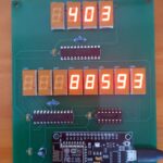
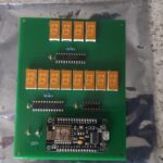
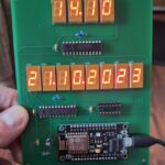
I have a couple of electronics projects in the works which use large LED displays and as they have a forward voltage of 8.4V and 20mA current they cannot be driven directly from a microcontroller using multiplexing. I could use a bunch of driver transistors or MOSFETS but that needs 14 pins on the microcontroller for a 6 digit display. So the reasonable option here is to use a chain of shift registers instead but the common 74HC595 is unable to drive the LED displays without external transistors. However there is the TPIC6B595 which has open drain outputs so can drive common anode displays and can sink up to 50V on each pin and at 500mA for the whole chip. Plenty to drive the 7 segment displays without multiplexing which is the solution I went for. Only 4 pins required on the microcontroller – yes technically only 3 for SPI but I wanted to control the Output Enable pin with PWM to adjust the display brightness.

The only problem is I’m wanting to build these projects for cheap and the TPIC6B595 is typically £10 each or £4.99 each on eBay. So I decided to take a risk and purchased 50 of them from a Chinese supplier on eBay who was advertising them as brand new for £3.96 for 10 plus £1.17 postage. That means for just less than £21 I’m getting them for £0.42 each. Bargain! Or not…?

Well they arrived after only 2 weeks via SpeedPak and I was immediately skeptical as to the description of “new”. On inspection most were obviously reclaimed parts as they were scratched, dirty and had a variety of date codes and font styles on the chip markings. The ones that did look new had a font completely different to the rest and no date code which later were found to have been blacktopped; a process where a chip is sanded down, painted and re-labelled. However despite all this on most of them the pins were in clean, good condition and none were bent so I’m assuming they were socketed in whatever device they were stripped from in the Chinese e-waste junkyard.

Skeptical, I made a test circuit that counted from 0-9 on a 7 segment display and to my surprise only 2 of them were dud. One of the duds was the suspected fake chip which *did* work in a fashion but upon powerup all of it’s outputs were on regardless of the OE pin logic level. It did go to normal once data was fed into it. The other had one output permanently shorted so it was always on. This looked like a genuine TI chip but it was obviously reclaimed as there was solder on the pins and part of the through hole plating of the PCB it was pulled from.

So, given the cost I got a bargain here. They were mis-advertised as “new” when they clearly were not but I wasn’t going to send them back and I gave the seller positive feedback, noting however they were not new parts. Having bought fakes before I’m always skeptical of cheap electronic components from eBay but I’m not complaining in this instance.

The seller I bought them from was cayin35 – I saved the seller and bought more parts such as IC sockets, resistors etc and these all turned out to be good.

Worth a look if you are wanting to save some money. I have no issues with buying parts like this as it re-uses parts that would otherwise end up in landfill or burnt saving the environment. A small drop in the ocean but every little helps right? If sellers were a bit more honest it would be better – maybe advertising them as used and tested? But if someone had to test them I guess that would put the cost up. But still, cheaper than UK suppliers.

Edit: due to me planning to sell some of my projects I purchased some genuine, new old stock chips from a UK supplier which worked out at around £2 per chip. These were fitted to two of the units I plan to sell on eBay and the reclaimed parts were used for the prototypes and future projects I’d be selling to friends and family.

Made another YouTube stats display / NTP clock thing…

Just a quick one today – I obtained a lot of orange 0.4″ retro LED modules so I thought seem as I have a few blank PCB’s left over from my previous YouTube counter display I thought I’d make another. This one was for test purposes to see what else I could use a 4 and 8 digit display for but I never got round to it. So I thought I’d sell the unused PCB’s and semi complete PCB’s on eBay. If you would like one of the semi complete PCB’s the link is below. Let me know if you want a blank PCB and I will list one for you.

I also made some clock firmware for it as well which gets the time from the global NTP server over Wi-Fi. It’s experimental and daylight saving time isn’t implemented but I’ll put the firmware on here for download if you want to experiment and adapt it for your own use.

Clock firmware

Original blog post for YouTube Counter

Please see my eBay listings link on the right where you can buy an assembled PCB or any other of my things that you may like!

How to determine the pinout of an unknown 7 segment display

If you have an unknown 7 segment LED display and you want to use it in your project, you need to determine its pinout. The pinout is the arrangement of pins that connect the display to the power supply and the controller. There are different types of 7 segment displays, such as common anode, common cathode, multiplexed, duplexed etc. Each type has a different pinout and requires a different wiring configuration.

In this blog post, I will show you a simple method to determine the pinout of any 7 segment LED display using a multimeter and some jumper wires. You will need:

– A 7 segment LED display
– A multimeter with a continuity tester
– Some jumper wires
– A breadboard (optional)

The steps are:

Continue reading →

Call centre calls waiting and LED matrix display teardowns

SDX ACD Wallboard
SDX ACD Wallboard

I recently acquired a few scrap Seltek (now Avaya) wallboards from an insurance company’s call centre, and they turned out to be quite intriguing. Among the items were three call waiting monitors and a SDX ACD scrolling message display, also known as a “wallboard.” What caught my attention were the separate LED modules in the scrolling message display, which seemed salvageable for either electronics projects or selling on eBay.

The MAX7219 chips
The MAX7219 chips

Inside the display, I found two matrix modules, each comprised of two lines with six 8mm square LED matrices featuring 5mm LEDs. These modules were controlled by a MAX7219 driver, and the entire system was controlled by a logic board utilizing an Intel 80C186 CPU. Additionally, there was a nice 5V power supply module and a toroidal transformer.

Unfortunately, I couldn’t establish a connection between the wallboard and my computer in its original state. Despite my attempts to uncover the serial protocol with some assistance from the YouTube user killergeek, I didn’t make any progress. I suspected that my USB to RS485 adapter might not be functioning correctly, or perhaps I wasn’t using the right baud rate. Nonetheless, the wallboard presented valuable components for future projects, and I’m considering using an Arduino to control the matrix modules. This would involve replacing the original logic board since it consists of a chain of MAX7219 displays. While each line possesses its own individual data and enable lines, the clock signals are shared between them. Alternatively, I could simply connect the output from the last MAX7219 of the top line to the input of the second line.

Continue reading →

Re-using a microcontroller from a LCDmodkit USB204B.V02 board

On one of my very old computers I had one of those LCDmodkit PC status screens that consisted of a 20×4 LCD housed in a 5.25″ bay and was interfaced to an internal USB header on the motherboard via a USB2LCD controller. As there are no Microsoft certified drivers available for this device it was no longer used in my newer Windows 10 or later machines. I removed the USB204B board off the back of the LCD and used the LCD for another project. That left me with a controller which was pretty much useless. On inspection I found it had an ATmega8 microcontroller and a bit of digging I found that this is based off the LCD2USB project by Harbaum (link to original project here) and it appears that the LCDmodkit controller is basically a redesigned original using SMT instead of surface mounted parts.

LCD204B controller mounted on perfboard

So I thought it is highly likely that the board could be reprogrammed and wasn’t locked. So I added a couple of headers to the former LCD connector and found, as in the schematic found on Harbaum’s project several of the I/O ports are broken out onto this connector. The rest are used for V-USB and serial and there is also a group of six solder pads labelled CN5 to the upper right of the microcontroller. I suspected this was for programming and poking around revealed this to be the case. The MOSI, SS and MISO pins were on these solder pads so I connected it to an arduino working as an ISP and uploaded a couple of basic sketches. Worked a treat but one thing to watch out for is the onboard crystal is 12Mhz not 16Mhz so anything that uses timers won’t work properly. However it’s great for very basic applications that involve sensors and activating outputs.

I’ve mapped out the six solder pads with pin one being to the right hand side of the photo. In other words pin one is nearest the edge of the board and pin six is nearest the microcontroller. I connected these via mod wire to a standard 6 pin ISP header on the perfboard.

Pins are 1= ADC6, 2= Reset, 3= MOSI, 4= SCK / SS, 5 = AVCC, 6 = MISO. 5V and power were taken from the 16 pin LCD header. The rest are easily found out by measuring continuity between each of the 16 pins and the pins on the microcontroller using a pinout as a reference. I used a 7805 regulator to power it but even if reprogrammed the original USB connector could be used to power the board.

Continue reading →

Nimrod MRA4 cockpit LCD display unit teardown (Thales LCD66N)

Whilst I was on covid lockdown I bought several avionics parts with the intention of making teardown videos and seeing if I could possibly power them up. If you are a frequent visitor to this site and / or my YouTube channel then you will already know this but for new visitors please check my other posts and my YouTube channel for more avionics teardowns.

I have a cockpit LCD display unit from an RAF Nimrod MRA4 which was a cancelled project to upgrade the existing MR2 aircraft which included new avionics and several aircraft were built but later scrapped before they entered service due to the project’s cancellation. Somehow many of the parts ended up on eBay and I’ve found by doing a little research these display units have found their way to home cockpit flight sim enthusiasts wanting to see if they can be used. Short answer to that question is possibly but from my teardown its likely they need a specialised video format and / or additional signalling to select inputs. My unit seems to be possibly faulty / broken as well but I will find that out once I get a power supply that can handle it as it draws over 5 amps at 28V. It’s explained in the YouTube video but for now here are some photos of the main boards.

Continue reading →

Teardown of a high end outdoor mast head Wi-Fi access point

Here I have a couple of defective enterprise grade access points that were decommissioned as they were suspected as faulty and were out of warranty. They are manufactured by Xirrus and are meant for outdoor high capacity Wi-Fi for public locations e.g. Stadiums, festivals etc. I thought I’d pull one apart and see what was inside before they were sent for scrap so I will share some photos here and give brief descriptions on what each major chip is and what it does.

I did a video below of the teardown but there is no narration. It’s good enough to get the point across but after all this is just an access point but a very expensive, enterprise grade one costing several hundred dollars.


Is it worth buying faulty tablets off eBay to repair & resell for profit?

I bought two lots of faulty laptops and tablets from eBay with the intention of repairing and reselling them as mentioned in my previous blog posts. Without repeating myself this was largely a success more so with the laptops and not so much with the tablets. The problem with the tablets not being profitable is because they are old and go out of date more quickly than laptops and the newer ones are more difficult to repair as they are usually glued together and cannot be taken apart easily. So, with this in mind I bought older models and avoided ones with obvious cracked screens. The majority of the faults were broken USB sockets which were replaceable but given the cost of the parts and eBay fees I only just broke even.

The other thing I found was some of these tablets had obviously come from computer repair shops and had missing parts and / or multiple faults as they had been used to make a good tablet out of several faulty ones and almost all parts in the ones I bought were faulty. Some were made to look like they had never been opened. Take this one for example; a Samsung  nexus 10 tablet which had a broken power / USB socket and a broken power button. I replaced the USB connector and power button but it still would not power up although the battery was charging. I removed the metal shield covering the CPU and flash chips and found that the flash chip had holes drilled into it. Now the seller had made a really good job of reassembling this tablet and making it look like it had never been opened. I was clearly ripped off here. Some of the others were in a similar state.

I thought I’d mention this for anyone who is thinking of buying faulty tablets to try and repair them. Watch out as most are junk unless you are buying from genuine private sellers selling three of them at most. Also they are often account locked and even if you fix them they are useless without being de-registered by the previous owner. This is why I avoid apple products but the latest Android devices are doing the same thing too.

So, take my advice. Don’t bother buying bulk faulty tablets and phones unless you like wasting your money.

More headaches – an Asus X205T that won’t boot from USB

I bought several laptops and netbooks off eBay with a view to refurbish and sell them; I got around 7 laptops and 9 tablets and netbooks for just £100. One of the netbooks was an Asus X205T that had it’s eMMC drive encrypted with bitlocker amongst other issues such as a dead battery and faulty keyboard. The netbook would only boot into the bitlocker recovery screen and would not allow booting from USB as it just returned to the bitlocker screen. To get around this problem and seem as I wanted to remove the existing data anyway I selected skip this drive on the bitlocker recovery which took me to the standard windows 10 repair recovery menu. Resetting the to factory settings was out as the storage drive was locked. So to get around this problem I went into the command prompt and removed all partitions with the DISKPART utility.

However upon rebooting the netbook just went straight into the BIOS and would not allow any boot options to be changed. It was set to USB for Windows to Go but would not boot anything. To cut a very long story short in order to get Windows 10 to install you must use a old USB2 stick (not USB3) and use the 32 bit version of windows. Only installation media created with the official Microsoft tool would work. Plugging this in and rebooting made it boot to the windows installer.

The reason for all this palaver is because the UEFI firmware is only 32 bit and will not see 64 bit code. Neither will it see USB3 pendrives, USB sticks etc. So if anyone ever has this problem now you know. This could apply to any older netbook and tablet running Windows 8.1 or later with a UEFI BIOS. See my previous post for a similar issue with a Dell Venue 8 Pro tablet.

Clean install of Windows 10 onto a Dell Venue 8 Pro tablet – major headache!

I had the unfortunate thing happen to my dell tablet computer – a windows “feature update” totally bricked it with a BSOD during install resulting in the tablet stuck on a screen saying windows encountered an unknown problem during installation or something like that. The only thing I could do was click OK which rebooted the tablet resulting in the same screen.

To cut a long story short this tablet originally came with Windows 8.1 and was upgraded to Windows 10 some time back. Now later builds of Windows 10 are not compatible with the Venue 8 pro unless you update the BIOS first. Too bad the windows installer didn’t detect this and went and installed the latest build anyway resulting in a bricked device. The original dell recovery partition was also overwritten when it was upgraded from Windows 8.1 to 10.

Now as this device only has one USB port which is also used for charging I had to fully charge the device and grab an OTG cable, a USB hub, a keyboard, a mouse plus a USB stick. To get windows to install I had to go into the BIOS by holding down volume down as the tablet starts up then releasing and changing the boot order to boot from USB. Now I had to download an older .iso using rufus which would work on this tablet then image it to a USB thumb drive. However once the setup started I was presented with a screen saying that an additional driver is required and the installer would not see the files on the USB stick despite booting from it. All I could see was the internal eMMC storage.

Continue reading →

Aircraft avionics teardown – Honeywell symbol generator

I obtained another interesting piece of aircraft avionics – this time a symbol generator computer that is used for generating the graphics and video signals for the CRT displays in the cockpit. From what I can gather there is typically 2-3 of these units in the aircraft with each symbol generator driving two displays so there would be one for each side of the cockpit + one backup.

It dates from around 1990 so it’s approximately 30 years old at the time of this article. The electronics inside are very space age with radiation hardened gold topped IC’s.

Video card (rear PCB)

It consists of various cards which are 2 x video driver boards, the CPU board, WXR scan converter board and several I/O boards. The computing technology isn’t anything to write home about but it would have been state of the art at the time. There is an Intel 80c86 used as the main CPU with some Zilog Z180 compatibles on the video cards.

Here’s a photo gallery with descriptions of the boards and a YouTube video

Continue reading →

NTP clock only version of my ESP8266 based display

As there was interest I have released firmware for my YouTube statistics and clock internet connected display featured in my previous post for users who just want an NTP clock and don’t require the YouTube counter functions. This clock automatically gets the time from the NTP server and synchronises it with the software based RTC running on the module every hour. A button toggles daylight saving time on and off.

The source code and pre-compiled .bin file can be downloaded in the links below. Use ESP8266flasher.exe tool to upload the firmware which is available on Github. I can’t post the file here but if you click on the link or google search for the tool it will show up. ESP flash tool settings set as follows:-

Baud rate 115200, flash size = 4Mb, DIO mode, 40Mhz (not to be confused with CPU clock speed) and finally flash to location 0x00000 as shown in the pictures below. Finally set the COM port on the operation tab and click the program / flash button.


Links to firmware

Internet clock (UTC / GMT timezone)

Internet clock (CET timezone)

Please contact me for other timezones.

Setup instructions and manual

Source code

Version 1.2 of the firmware and source code. In this version I added a DST mode on / off indicator on the rightmost decimal point of the display. The download link is for the UTC / GMT timezone. Contact me for other timezones.

Licence: creative commons attribution-non commercial (CC BY-NC)