SPI driver board for large 2-8″ 7 segment displays

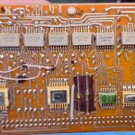
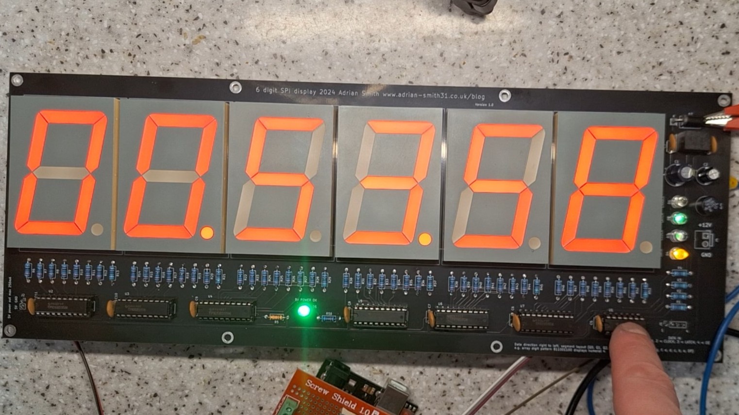
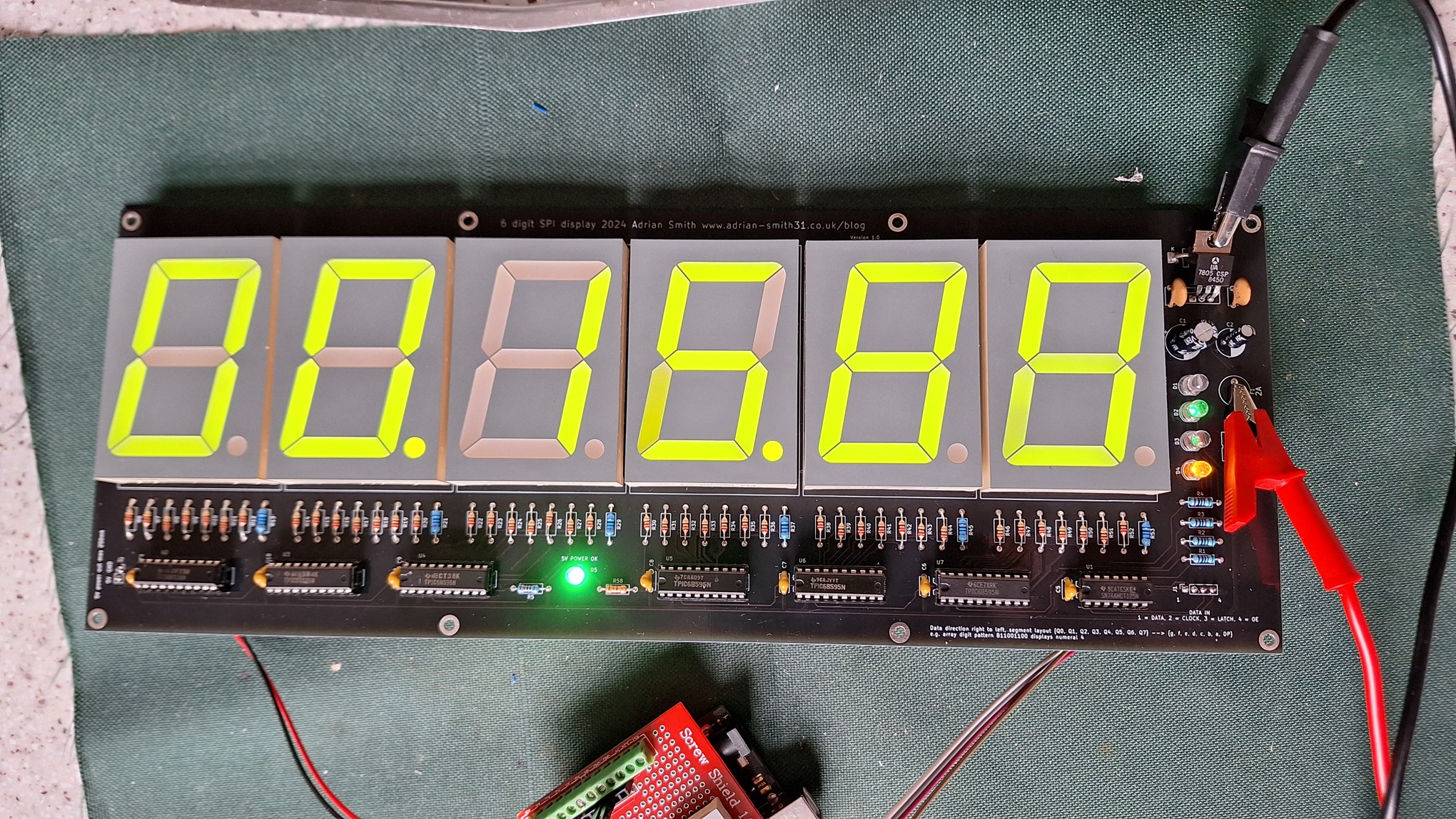
As part of a collaboration project through contact with a member of Instructables who had seem my large LED clock project I made some serial driver boards for his project adapted from mine which uses 4″ high LED displays and uses the decimal points as the colons with alternate digits inverted. These driver boards are daisy chainable and can be used for driving any large, multi LED chip 7 segment displays. A TPIC6B595 serial shift register is on each PCB with the aim that the boards can be mounted behind or to the displays. Control can be from an Arduino, Raspberry Pi, ESP32 etc.

Completed PCB (version 1)

I will be selling these boards on eBay and / or Tindie if you wanted to purchase some for your own projects. Please see the links on the right for my eBay store where you can purchase a blank, unpopulated PCB.

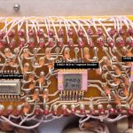
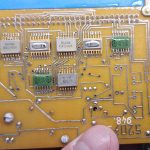
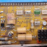
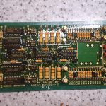
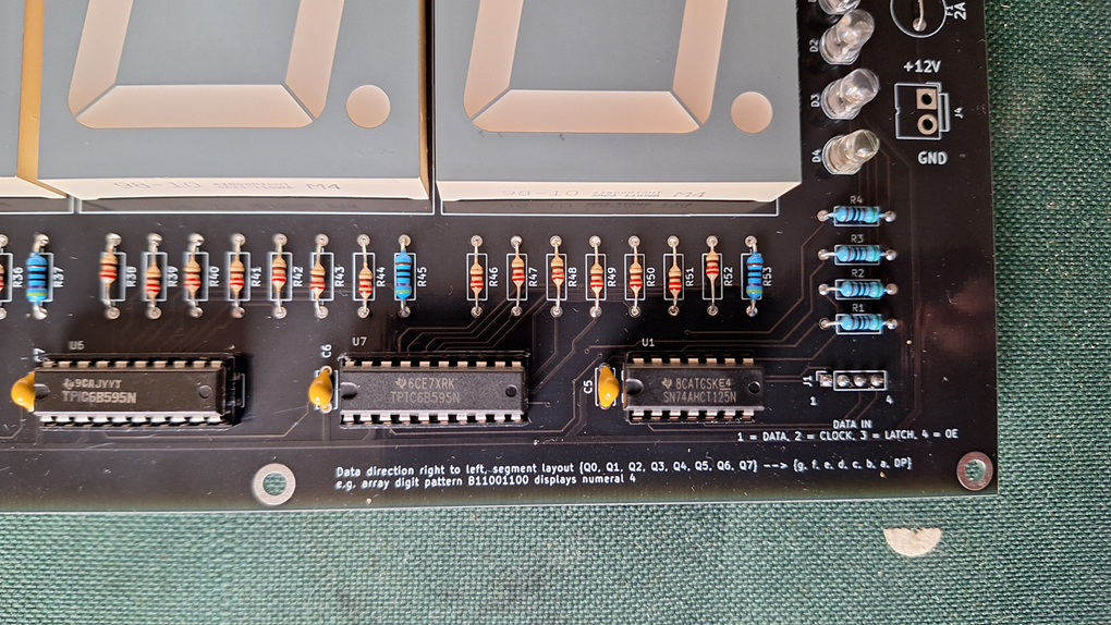
The PCB is basically a breakout board for the TPIC6B595 and has provision for current limiting resistors on the LED segments. As the TPIC6B595 is a sink driver, these boards can only be used with Common Anode displays. They are daisy chained by simply plugging them together. There is a 10K pullup resistor attached to the SRCLR pin which in most cases can be left as-is and not connected to the microcontroller as the SPI libraries do not use this pin. It is broken out onto the input and output connectors if the user wishes to use it. The 10K resistor should only be fitted to one board if daisy chained.

Filter & smoothing capacitors are fitted to each PCB with a 0.1uF and 10uF capacitor on the 5V rail and a 33uF capacitor on the LED anode supply, which in most cases 12V is fine. The 4″ LED modules used in Rick’s project have 5 LED chips per segment and one for the decimal point so 330ohm resistors for the segments and 1.2K for the decimal point is required for a forward current of around 8mA. With his displays this gives a very bright display – in fact too bright. With my firmware the brightness can be controlled by using PWM on the Output Enable pin.

Continue reading →

Teardown of Royal Air Force (UK) ATC control console panels

A while back I got part of a communication console unit that was ex military. Not being able to find anything on it at the time I later found out it was part of the desk consoles used for Air Traffic Control for the RAF. I later bought two more units that were slightly different as the previous unit had some useful MM5450N constant current LED driver chips in them which could be salvaged for Arduino projects. These chips are basically a chain of shift registers so could easily be used for driving a 4 digit LED display.

I thought I’d post the videos of the teardowns if anyone is interested.

Video of the two later units

Harrier GR5 engine diagnostic computer DRU unit teardown

Here I have a PRS-2026C Data Retrieval unit which is part of the GEC-Marconi (formerly Plessey Avionics) ESD2020 system used for fault diagnosis and servicing of the Harrier GR5 and the AV8B aircraft. These are no longer used by the air force and find themselves onto eBay and other military surplus sites. I was donated one for a teardown video so I thought I’d take a look inside.

This is actually just the Data Retrieval Unit which is carried around by the ground maintenance crews and connects to another box inside the aircraft. There is a hand held keypad and a 2×16 LCD screen to operate the unit. It is a single board computer system based on the Motorola MC68008 which is the 8 bit version of the MC68000 running at 8Mhz. There are two ROMS; one containing the real time operating system by Silicon Software and the other containing the application. There is also 1Mb of EEPROM storage for storing the aircraft engine data. There is 256Kb of SRAM to complete the main components. Aside from the usual UART and interface IC’s there’s some 74 series glue logic and a couple of CPLD chips.

The Main Unit. Credit to Neil Roberts

There’s no video output on this unit and data is sent to / from the aircraft over RS-423 with Manchester encoding. The keypad and LCD communicates via RS422. There are also 4 additional RS232 serial ports at TTL levels which go to a user port used for downloading the data to a PC and a printer. I also dumped the EEPROM storage and found some aircraft tail numbers amongst other data but most was meaningless to be honest.

Credit to Neil Roberts who also has one of these units and kindly sent photos of it working with the hand held keypad. It is easily powered as the board runs entirely off 5 volts and on the other side of the case there is a DC-DC converter which converts the aircraft 28V DC to the 5V required. It also has an optional 24V battery pack which was not fitted so I powered it up by connecting a bench PSU to the battery terminals.

Not sure what I’m going to do with it but it might make a great hacking project. Here’s a few photos and some YouTube videos.

Continue reading →

Requesting help via comments / contact me form

I have had several enquiries via the contact me form where mostly users have been asking me for technical help on some of my articles where they have a similar device and wanted my help in helping them getting it to work or wanting assistance building one of my projects.

To cut a long story short, I do read all the emails and I have written lengthy replies to technical queries especially for the Data Display LED display boards but I have not had any replies to my emails sent in response, not even a thankyou for your help, nothing.

If I go out of my way to respond to your email and spend my time providing a detailed response at least have the common curtesy to acknowledge my help in your technical issue. I do this free of charge but if this happens again I will turn comments off and will not respond to any technical queries via the contact me form.

If you want to contact me for help, please have the curtesy to reply to my response and / or acknowledge my help. Otherwise I’m just wasting my time.

Thanks

Russian Avionics ARK-22 Radio Compass teardown

In this teardown article I have a Russian ARK-22 radio compass control box which was part of the avionics and miscellaneous items I was donated for my YouTube channel. I have not taken any Russian avionics apart before so this was an interesting find. It took a while to find some information on this unit and since publishing the video, a viewer Nick managed to find some more information on this unit and sent me some scanned PDF’s some of which were partially translated into English.

The ARK-22 is a rudimentary navigation system which uses directional radio beacons for navigation. It works by the pilot tuning to a particular frequency or channel of a radio beacon and the system can tell the approximate location of the aircraft going by the signals from the beacon. This system is now almost obsolete having been replaced by more modern radio and GPS based systems. It consists of several LRU’s but I only have the control box. The documents below give some information on the complete system.

Photos of the circuit boards

PDF and other downloads

.zip file containing theory of operation, user manual, partial schematics and rear connector pinout here.

Youtube Video


Vandling / Global NDB-2 aircraft navigation unit teardown

More aircraft avionics to take a look at again. This time we have a Global NDB-2 which is an optional unit for the GNS-500A navigation system commonly fitted to private business jets. This unit is a “databank” containing coordinates and other information for over 20,000 airports and airfields worldwide. It consists of a main unit and a removable memory unit which can also be upgraded via floppy disks. Yeah this thing is old – dates from the early 1980’s.

The memory unit contains a Z80 CPU with an EPROM containing the firmware, 64Kb of RAM and 256KB of battery backed SRAM for storing the database. The main unit consists of 2x ARINC-429 interface boards, a CPU board and a DC-DC converter. The CPU board is powered by a Motorola 6809 CPU and has three RS422 interfaces, two of which go to the rear panel and the other to one of the ARINC boards.

I also dumped the EPROMS and ran them through a disassembler to get Z80 and 68xx assembly code. They can be downloaded here.

Photos of the boards

Video

Large 2.3″ 6 digit 7 segment display board for hobbyists

This project came to being when I wanted a large multi digit 7 segment LED display but I was only able to find MAX7219 or similar based display boards with digit heights up to 0.56″. Not being able to find what I wanted, I decided to make a 6 digit clock (one of my earlier projects) and as I had some larger 2.3″ displays spare I designed another 6 digit display this time with just the SPI interface so it can be connected to any microcontroller with a SPI interface.

To keep costs down I decided against using external drivers with a MAX7219 and instead went with a chain of shift registers using TPIC6B595’s as their open drain outputs can sink up to 500mA (shared between all 8 outputs) and up to 50V – ideal for the large LED displays that have a forward voltage of 8.4V. The PCB would have to be powered from 12V due to the higher voltage displays so a 7805 regulator provides the 5V power for the shift registers and the input buffer which also translates 3.3V logic levels to 5V required by the shift registers.

The board is suitable for electronics hobbyists and it provides ultra bright LED’s on the data input lines to indicate input signal status. With input signals that have a very low duty cycle the status LED’s would not light hence why ultra bright LED’s were used. Ideal for testing and development use and for use in a final, one off project. It runs off 12 volts and has an onboard regulator for the IC’s. It is compatible with 3.3V and 5V logic level inputs on the data connector.

The board was also designed with through hole components for ease of assembly and features a reverse polarity protection diode and a 5V output for powering an Arduino or similar. Current consumption with all digits and segments on is around 700mA. A 12V regulated power supply rated at 2A is needed to power this board.

I will be selling these on eBay as I build them and also maybe as kits – please see my listings to the right.

This project was sponsored by NextPCB.com who kindly made the PCB’s for them. They are good quality and are made with black soldermask. As this project is no longer being made by me and sold on eBay I have released the Gerber files.

Demo code

SPI Display Board Instructions

Gerber files

YouTube video

Plessey PV1754X military radio control box teardown

In a various spending spree of avionics I bought on eBay I have a radio control box for a Plessey PTR-1751 military radio, a common unit used in several aircraft including helicopters during the 1980s and 1990’s. The radio has 7000 channels across 25khz intervals as well as AM reception on 243Mhz for emergency use. It has a power output of 10 or 20 watts and is powered from a 28V supply. Now the main unit is missing and I only have the main control box which features a 5 digit “Numitron” display which are incandescent filament 7 segment displays, which are still preferred in some uses due to their readability in a variety of conditions including night vision goggles.

Electronics wise it consists of several circuit boards populated with mainly 4000 series CMOS chips, some PLL synthesizers, transistor arrays and a custom 40 pin IC labelled NOM402L made by Mitel semiconductor which is some sort of programmable logic array.

Here are some photos and a YouTube video of the teardown.

YouTube Video

Connecting vintage incandescent (filament) displays to a microcontroller

I’d thought I’d share these cool retro 7 segment displays I obtained from an old aircraft radio. They are Wamco KW-104S direct view incandescent filament displays which are compatible with LED display driver code – just treat them like common anode 7 segment LED displays. Easy! You just have to bear in mind that they need an operating voltage of 4 volts and they draw around 15mA per segment. Due to their self current limiting nature, they do not need current limiting resistors between the driver chip and the display. Note I said driver chip as with the current drawn from these displays you are best using a power shift register such as the TPIC6B595 or a transistor array rather than driving them from the microcontroller or shift register pins directly.

A datasheet can be found here https://www.wamcoinc.com/assets/pdf/Display%20Catalog.pdf

Some images and a video


Multiplexing 7 segment displays with a shift register and transistors

In this example I will show you how to multiplex a 7 segment LED display from a microcontroller such as an Arduino without placing too much load on the microcontroller pins as I have seen in some other examples. Quite a few tutorials I’ve seen are not really good practice for electronics design – some even don’t use current limiting resistors!

Direct method (commonly seen in a lot of online examples)

A multiplexed display can be run directly from a micro without a shift register as long as the current limit of the microcontroller pins is observed, in the ATMega328’s case is 20mA typical, 40 absolute maximum per pin. But you have to watch out for the total current allowed per port and for the whole chip to avoid excessive power dissipation leading to bonding wire failure or the magic smoke. In this configuration the segments are driven from one set of pins and the digits another. This method uses a lot of pins on the microcontroller and in most cases can overload the pins used for the digits. Hence this is only suitable for 2-4 digit displays and limiting the average current per segment to 5mA or less. High efficiency LED displays are required for this method otherwise you will have a dim display. So, to solve the problem of overloading the pins on the microcontroller, transistors are a must for the digit selection as, with all digits on showing 8. 40mA could flow through one pin if an average of 5mA were to be used. This is right on the absolute maximum for the microcontroller. A PNP transistor (common anode) or NPN transistor (common cathode) is recommended. An example circuit is shown above.

One thing that you have to remember with multiplexing a single digit is only on for x number of total digits e.g. a 4 digit display is only on for 1/4 of the time so you would need to increase the current by 4 times so the segment current needs to be 20mA. That times 8 segments is 160mA – OK for some of the ports on the ATMega328P but the chip has an absolute maximum of 200mA for the whole chip. This limits the amount of current and the number of digits on your display. You could use a driver chip like the MAX7219 instead (which I really would recommend) but this isn’t the subject of this article.

Continue reading →

A digital scale controller for HX711 modules up to 99.999Kg

I was experimenting with load cells for a commercial project and thought I’d share one of the prototypes I built to test HX711 load cell modules. It’s built on Veroboard but I designed a PCB for it however never got it manufactured as you can buy one on AliExpress for around 3 Euros or a fiver on eBay so I didn’t see much point into going to the expense. This design uses an ATMega328P like my other version and a TPIC6B595 to drive the segments. PNP transistors drive the digits via multiplexing. You are free to check it out, use and adapt my code and design files as you wish but if you do end up using my design and publishing it online please give me credit in the description to say it has been adapted from my design.

As a matter of interest the other design used a differential amplifier to convert the voltage from the load cell to single ended and amplify it 100 times so it could be interfaced to an ATMega328P. It was designed to weigh each wheel of a race car by using 4 load cells making a scale for each wheel. This was so you could balance the weight distribution for better handling. We went with that design in the end so the spare HX711 modules had some other use. Which was to make my own scale for items up to 10Kg.

After building it I found that plastic is not the best thing to bolt the load cell to – it needs a stable surface that does not flex or bend such as thick steel or aluminum. But anyway whilst I can’t release my commercial project details to the public I can release information of the prototype I did not use. After all I ended up using it to weigh small items to calculate eBay postage costs and even with the plastic case it can weigh up to 5Kg accurately.

Another thing to watch out for –  I used 7 segment displays with a forward voltage of 2.2V and 47 ohm current limiting resistors giving a segment current of around 60mA which x8 segments if all lit is close to the absolute maximum of 500mA for the TPIC6B595. I would suggest if you were to make this project, use higher efficiency 7 segment displays (most modern ones are bright enough at 8mA per segment) and use 68 ohm resistors instead to reduce load on the TPIC6B595. Note I said 8mA per segment but with multiplexing over 5 digits it needs to be 8mA x 5 digits = 40mA. With a forward voltage of 1.8V that’s 5V – 1.8V = 3.2V / 68 ohms = 47mA. 47mA / 5 digits = 9.4mA which is close enough. 47 x 8 segments = 376mA which is safe enough for the shift register to handle.

Credit goes to Olkal for the HX711 library which you can find here GitHub – olkal/HX711_ADC: Arduino library for the HX711 24-bit ADC for weight scales including how to calibrate the scale for your setup.

Links and photo gallery

HX711 code (C++)

Weigh Scale Controller Gerber files

Complete project files (KiCad)

YouTube video

Build a large 6 digit clock using 1.8″ + 0.8″ LED displays and TPIC6B595 shift registers

The project

I recently bought a few LED displays as a job lot which were parts for fruit machines; the type you see in the local pub and after testing them I found that they had a nice bright red / orange colour to them and decided to use them for a large clock project. As I have not made anything for a while and had some spare time on my hands I thought I’d need to brush up on my PCB design skills and C++ coding skills. Hence this project – a large LED clock which uses 1.8″ high digits for the hours and minutes and the seconds is displayed on 0.8″ 7 segment displays. It is controlled by an ATMEGA168P microcontroller and uses TPIC6B595 shift registers to drive the common anode displays. A DS3231 high precision RTC completes the electronics. It is a large PCB measuring 270x120mm and can easily be seen from 30 feet away making it suitable for large workplaces or people with limited vision. The clock is powered from a 12V regulated power supply which can supply 800mA or more. A fuse and reverse polarity protection diode helps to prevent incorrect power supply connection from damaging the components. Finally three buttons are used for setting the time. There is provision on the PCB for a 4th button which could be used for something else if I wanted to add extra features later or with the code being open source you could make use of it yourself should you make one.

This project was sponsored by PCBway who kindly offered to make the PCB’s for them. As I have already made the prototypes using boards from JLCPCB I decided to take up their offer and made a slight design change to the PCB layout. I plan to sell these PCB’s along with the remaining version 1 PCB’s on eBay / Tindie so you can make your own if you wish. Please see the links to the right for my eBay store where you can purchase one along with a completed, assembled PCB which I will list in the coming weeks once the button boards and new TPIC6B595 chips come into stock. The version 1 PCB’s are made in green solder mask whereas version 2 has black solder mask. The source code and schematic I will show below and also there is a YouTube video explaining how the circuit and code works.

Continue reading →